
Method for automatically updating element stereogram on printed circuit board

A printed circuit board, automatic update technology, applied in the direction of electrical digital data processing, special data processing applications, instruments, etc., can solve the problems of human error, increased time spent, etc., to reduce the time spent and reduce human verification errors. Effect

Inactive Publication Date: 2008-06-18
INVENTEC CORP
View PDF0 Cites 0 Cited by
  • Summary
  • Abstract
  • Description
  • Claims
  • Application Information

AI Technical Summary

Problems solved by technology

However, with the accumulation of time, the amount of files produced based on the modified names of component physical diagrams will increase. Therefore, layout engineers can only use manual methods when facing different types of printed circuit boards and their versions. One by one, check whether there is a component physical diagram that needs to be updated on the printed circuit board of each model. It is conceivable that because of the manual check, there will be some human errors, and the time spent will also increase. Increase

Method used


Image

  • Method for automatically updating element stereogram on printed circuit board

Examples


Embodiment Construction

[0008] The technical effect that the present invention intends to achieve is to solve the problems described in the prior art

[0009] When the printed circuit board needs to update the physical diagram of the component, it can only be manually compared one by one to check whether there is a physical diagram of the component that needs to be updated on the printed circuit board of each model. The following content will be A detailed description of the technical features and intended effects of this case is provided for reference by those skilled in the art related to the invention.

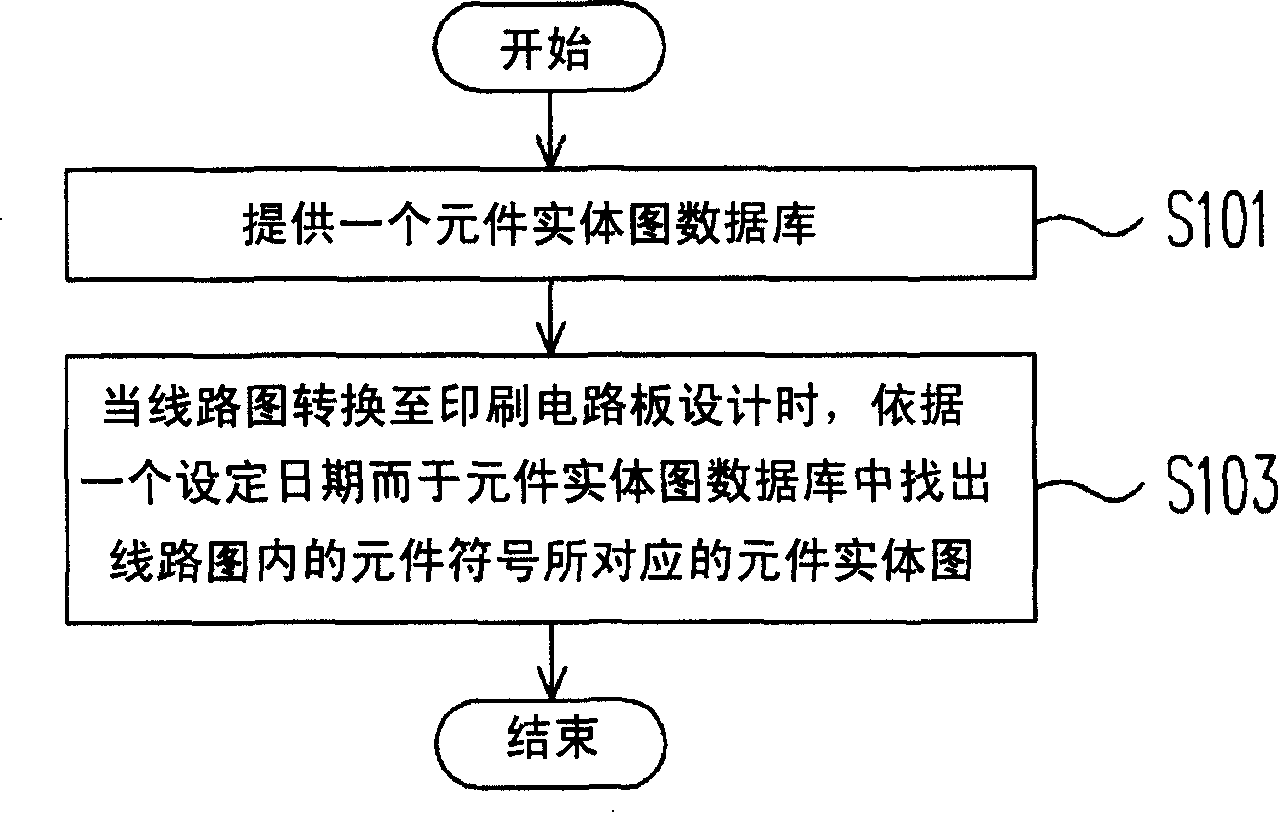
[0010] figure 1 It is a flow chart of a method for automatically updating a component entity diagram on a printed circuit board according to a preferred embodiment of the present invention. Please refer to figure 1 , the method for automatically updating the component entity diagram on the printed circuit board includes the following steps: first, as described in step S101, a component entity di...


PUM


Abstract

The invention discloses a method used for automatically updating the stereogram of elements on a printed circuit board. The method includes the following steps: firstly, a database of the element stereogram is provided, wherein the data in the database of the element stereogram is set up according to date sequence; then when the circuit diagram is switched to the design of the printed circuit board, the element stereogram corresponding to the element symbol in the circuit diagram is searched out from the element stereogram database according to a set date, thereby achieving the purpose of automatically updating the stereogram of the elements on printed circuit board and further reducing the errors caused by human check, furthermore, the consumed time can also be reduced.

Description

technical field [0001] The present invention relates to a method for updating the entity diagram of components on a printed circuit board, and in particular to a method for automatically updating the entity diagram of components on a printed circuit board. Background technique [0002] Generally, after the trial production of the production line, there is often a situation of modifying the component geometry on the printed circuit board (PCB), so the person responsible for modifying the component geometry will make a file with the modified component geometry name and notify the layout (layout) ) engineer to modify the corresponding circuit diagram file. However, with the accumulation of time, the amount of files produced based on the modified names of component entity diagrams will increase. Therefore, layout engineers can only use manual methods when facing different types of printed circuit boards and their versions. One by one, check whether there is a component physical...

Claims


Application Information

Patent Timeline
Patent Type & Authority Applications(China)
IPC IPC(8): G06F17/50
Inventor 蔡淑芬陈惠玲
Owner INVENTEC CORP
Learn More