Casing structure of CD ROM

A casing and optical drive technology, applied in the direction of record carrier structural parts, instruments, data recording, etc., can solve problems such as failure to pass certification, insufficient structural strength, easy to scratch optical discs, etc.

Inactive Publication Date: 2008-06-18
QUANTA STORAGE INC
View PDF0 Cites 1 Cited by
  • Summary
  • Abstract
  • Description
  • Claims
  • Application Information

AI Technical Summary

Problems solved by technology

However, the position where the volume label 17 is pasted requires sticking to the center of the upper surface of the casing 11 of the optical drive 10, so that the label 17 seals the through hole 16, thereby causing the air pressure near the center of the optical disc 14 inside the optical drive 10 to drop, causing the optical drive to Atmospheric pressure outside 10°C pushes the casing 11 near the center of the optical disc 14 to be concave (as shown by the dotted line). This phenomenon is very easy for optical drives with insufficient structural strength of the casing to achieve light weight due to this phenomenon. Appear
Excessive concave deformation of the casing 11 will not only produce permanent deformation, but also affect the flatness of the optical drive casing, fail to pass the certification, and scratch the optical disk 14 more easily
Therefore, there are still problems to be solved urgently in the structure of the casing of the existing optical drive.

Method used


Image

  • Casing structure of CD ROM
  • Casing structure of CD ROM
  • Casing structure of CD ROM

Examples


Embodiment Construction

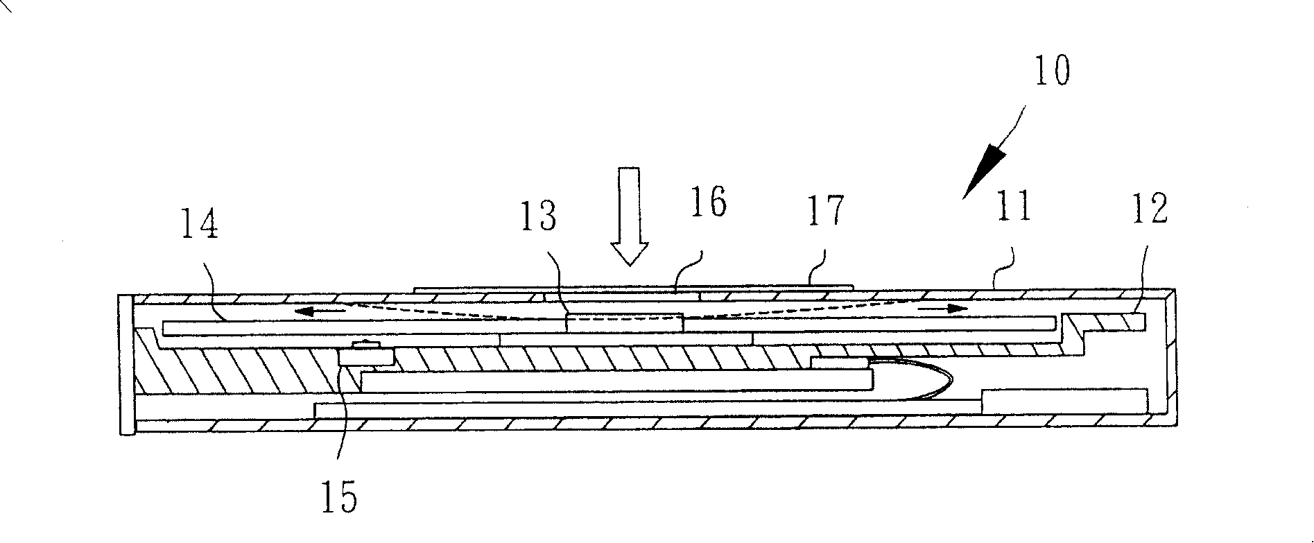
[0034] Regarding the present invention in order to achieve the above object, the technical means adopted and the effects thereof, preferred embodiments are given hereby, and are described as follows in conjunction with the drawings.

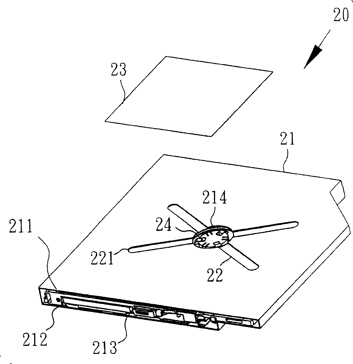
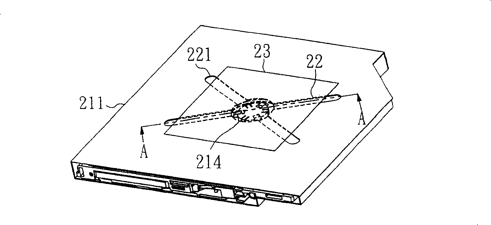
[0035] Please refer to figure 2 , which is the optical drive casing structure 20 of the first embodiment of the present invention. The optical drive casing structure 20 includes a casing 21, an air passage 22 and a label 23, mainly forming an air passage 22 on the casing 21. When the air passage 22 is covered by the label 23, the air passage 22 can still supply air to the optical drive. inside, to balance the air pressure.

[0036] Wherein, the casing 21 includes an upper casing 211 and a lower casing 212, the upper casing 211 covers the lower casing 212, and the inner portion 213 of the optical drive is formed in the middle, and a spindle motor 24 is housed in the center of the optical drive inner portion 213. Rotate a disc 25 (please refer t...


PUM


Abstract

The invention discloses a CD-ROM driver casing structure, consisting of an upper casing and a lower casing. A main shaft motor is arranged in the casing. The upper casing is positioned above the main shaft motor and is provided with a through hole. A plurality of air channels are separately arranged around the through hole on the upper casing. A downward depression of the casing forms a lower groove, and one end of the groove is communicated with a neighboring part of the main shaft motor through the through hole and the other end is a communication port. A label is adhered to the casing to cover the air channels and the through hole, One end of the communication port of the air channel is extended towards the edge of the casing and the communication port is preserved beyond the covering area of the label so as to balance the pressure difference between the internal and external parts of the CD-ROM driver.

Description

technical field [0001] The invention relates to an optical drive, in particular to an optical drive shell structure which forms an air channel to balance the air pressure inside and outside the optical drive and reduce the deformation of the shell. Background technique [0002] With the rapid increase of data storage capacity of optical drives, the speed must be increased to maintain a certain reading and writing efficiency, and the high-speed rotating optical discs can easily drive the surrounding air flow, resulting in an imbalance in the internal pressure of the optical drive, and even vibration noise If it is serious, it will even affect the flatness of the optical drive, causing damage to the optical disc. [0003] Such as figure 1 Shown, it is an existing optical drive 10, a tray 12 is accommodated in the hollow casing 11, a spindle motor 13 is arranged at the center of the tray 12, and the spindle motor 13 clamps an optical disc 14 by the center, and at a high speed ...

Claims


Application Information

Patent Timeline
Patent Type & Authority Applications(China)
IPC IPC(8): G11B33/02G11B33/08
Inventor 王友圣吴仁琛黄国玮
Owner QUANTA STORAGE INC
Why Eureka
Try Eureka