Intelligent belt pulley

A technology of intelligent belts and pulleys, applied in belts/chains/gears, components with teeth, portable lifting devices, etc., can solve the problem that the reducer is difficult to meet the long-stroke, low-stroke pumping unit, etc., and achieve mechanical strength. protective effect

Inactive Publication Date: 2008-06-25
樊世耀 +1
View PDF0 Cites 9 Cited by
  • Summary
  • Abstract
  • Description
  • Claims
  • Application Information

AI Technical Summary

Problems solved by technology

[0003] In order to solve the problem that the reducer and belt transmission mechanism used in the existing beam pumping unit are difficult to meet the needs of long-stroke and low-stroke pumping units, and the energy-saving requirements of the matching small-power motor, the present invention provides a motor that can be used from zero Intelligent pulley for fast start and real-time detection and recording of reducer load

Method used


Image

  • Intelligent belt pulley
  • Intelligent belt pulley
  • Intelligent belt pulley

Examples


Embodiment 1

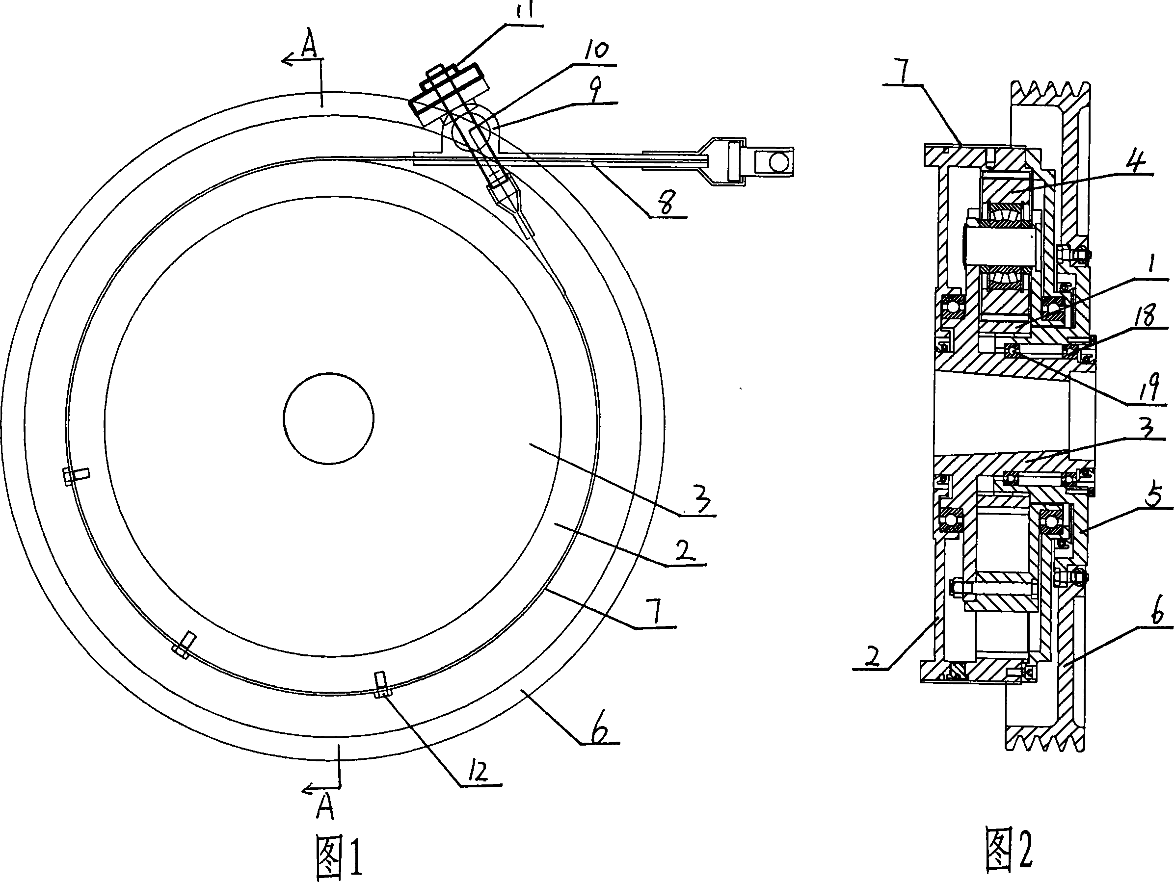
[0020] As shown in Figure 1 and Figure 2, the smart pulley includes a planetary gear mechanism consisting of a sun gear 1, an inner ring gear 2, a planetary carrier 3, and a planetary gear 4, and a pulley consisting of a pulley core 5 and a pulley 6. The pulley core 5. The bearings 18 and 19 are axially fixed to the planet carrier 3, the sun gear 1 is floatingly connected to the pulley core 5, and the inner ring gear 2 is wound with a friction belt 7, and one end of the friction belt 7 is provided with a connecting plate fixed on the reducer body 8, the other end is fixed with a screw 10 passing through the connecting plate 8 and fixed by a nut 11. The friction belt 7 is fixed with the ring gear 2 by bolts 12 . The coupling plate 8 is provided / opened with a collar 9 through which the screw rod 10 passes. At this time, the smart pulley only has the function of deceleration. Generally, its own deceleration ratio is set at 3-5. It is used on the decelerator, which is equivalent ...

Embodiment 2

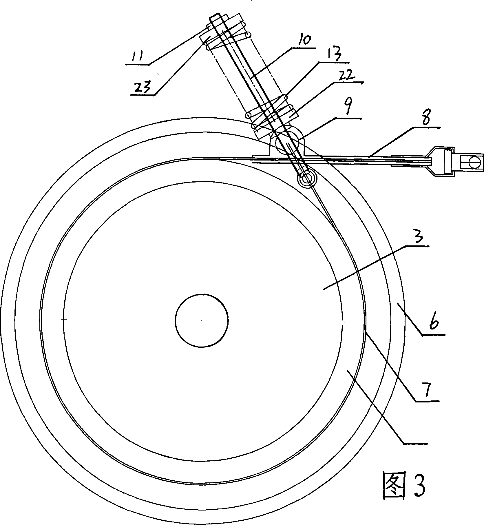
[0022] As shown in Figure 3, the smart pulley includes a planetary gear mechanism composed of a sun gear 1, an inner ring gear 2, a planetary carrier 3, and a planetary gear 4, and a pulley composed of a pulley core 5 and a pulley 6. The pulley core 5 passes through the bearing 18, 19 are axially fixed with the planet carrier 3, the sun gear 1 is floatingly connected with the pulley core 5, and the inner ring gear 2 is wound with a friction belt 7, one end of the friction belt 7 is provided with a connecting plate 8 fixed on the reducer body, and the other One end is fixed with a screw rod 10 passing through the connecting plate 8 and fixed by a nut 11 . A compression spring 13 is sleeved between the nut 11 on the screw 10 at the end of the friction belt 7 and the connecting plate 8, and the two ends of the compression spring 13 are provided with washers 22 and 23, and the compression of the compression spring between the two washers can be adjusted through the corresponding op...

Embodiment 3

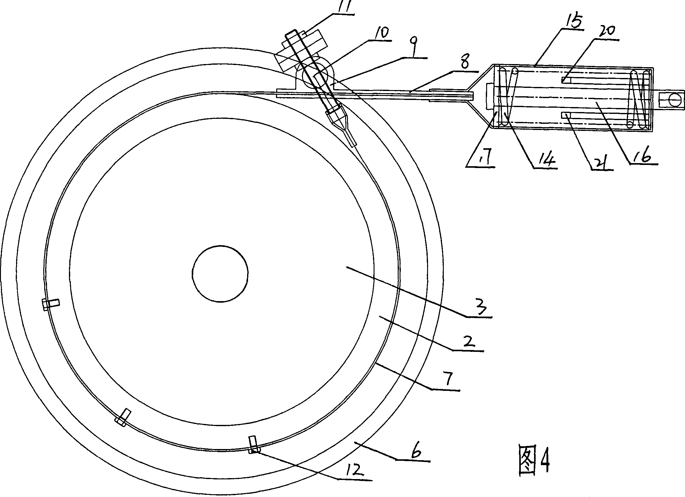
[0024]As shown in Figure 4, the smart pulley includes a planetary gear mechanism composed of a sun gear 1, an inner ring gear 2, a planetary carrier 3, and a planetary gear 4, and a pulley composed of a pulley core 5 and a pulley 6. The pulley core 5 passes through the bearing 18, 19 are axially fixed with the planet carrier 3, the sun gear 1 is floatingly connected with the pulley core 5, and the inner ring gear 2 is wound with a friction belt 7, one end of the friction belt 7 is provided with a connecting plate 8 fixed on the reducer body, and the other One end is fixed with a screw rod 10 passing through the connecting plate 8 and fixed by a nut 11 . The friction belt 7 is fixed to the ring gear 2 through bolts 12; an overload power-off protector is arranged on the connecting plate 8, and the overload power-off protector includes a housing 15 fixed to the connecting plate 8 at one end, and the housing 15 is provided with The contacts 20 and 21 that make the motor power supp...


PUM


Abstract

The invention relates to a belt pulley in a belt driving mechanism, in particular to an intelligent belt pulley for walking beam type pumping unit in oil fields. The invention solves the problems that: the prior speed reducer and belt driving mechanism for walking beam type pumping unit can not meet the requirements of long-stroke low-frequency pumping units and the energy-saving requirements of a matched low power motor. The intelligent belt pulley comprises a planet gear mechanism consisting of a sun wheel, an annular gear, a planet carrier and a planet gear, and a belt pulley consisting of a belt pulley core and a belt pulley, wherein the belt pulley core is axially fixed on a planet carrier shaft through a bearing, the sun wheel is in floating connection with the belt pulley core, the annular gear is surrounded by an external friction tape, one end of the friction tape is fixed on a connecting plate on the body of the speed reducer, the other end of the friction end is fixed on a screw which passes through the connecting plate and is fixed through a nut. The invention which has reasonable and simple structure, high mechanical efficiency and lower power consumption can meet the requirements of long-stroke low-frequency pumping units in various types of oil fields and is also applicable to other universal machines.

Description

technical field [0001] The invention relates to a belt pulley in a belt transmission mechanism, in particular to an intelligent belt pulley used for a beam pumping unit in an oil field. Background technique [0002] Most of my country's oil fields are low-energy and low-yield oil fields. Unlike foreign oil fields, which have strong self-spraying capabilities, most oil fields rely on water injection to press oil into the well, and pumping units (also known as kowtow machines) pump oil from the formation. Raise up. At present, the number of pumping units in my country is more than 100,000, the total installed capacity of electric motors is 3500MW, and the annual power consumption exceeds 10 billion kW·h. At present, the operating efficiency of pumping units is extremely low, with an average operating efficiency of 25.96% in my country and 30.05% abroad, and the annual energy saving potential can reach several billion kW·h. In recent years, the number of heavy oil wells, gas-b...

Claims


Application Information

Patent Timeline
Patent Type & Authority Applications(China)
IPC IPC(8): F16H55/36F16H37/00F16H35/10
Inventor 樊世耀任晓明
Owner 樊世耀
Why Eureka
Try Eureka