Supercharge Your Innovation With Domain-Expert AI Agents!

Wave filter circuit

A filter circuit, impedance matching circuit technology, applied in electrical components, transformer/inductor coils/windings/connections, impedance networks, etc., can solve problems such as inapplicability, excessive consumption of components, and insufficient performance

Inactive Publication Date: 2008-06-25
DELTA ELECTRONICS INC
View PDF0 Cites 5 Cited by
  • Summary
  • Abstract
  • Description
  • Claims
  • Application Information

AI Technical Summary

Problems solved by technology

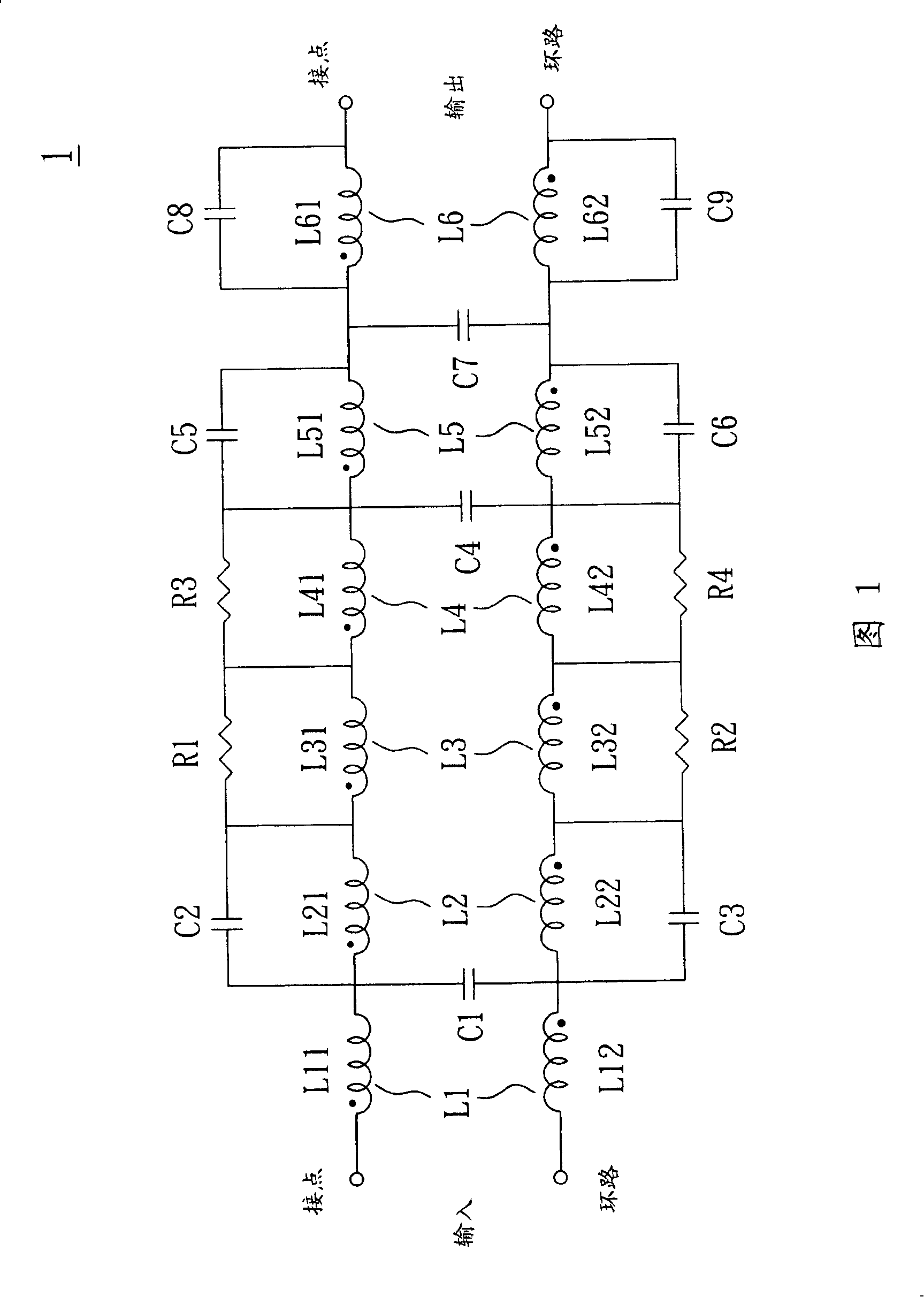
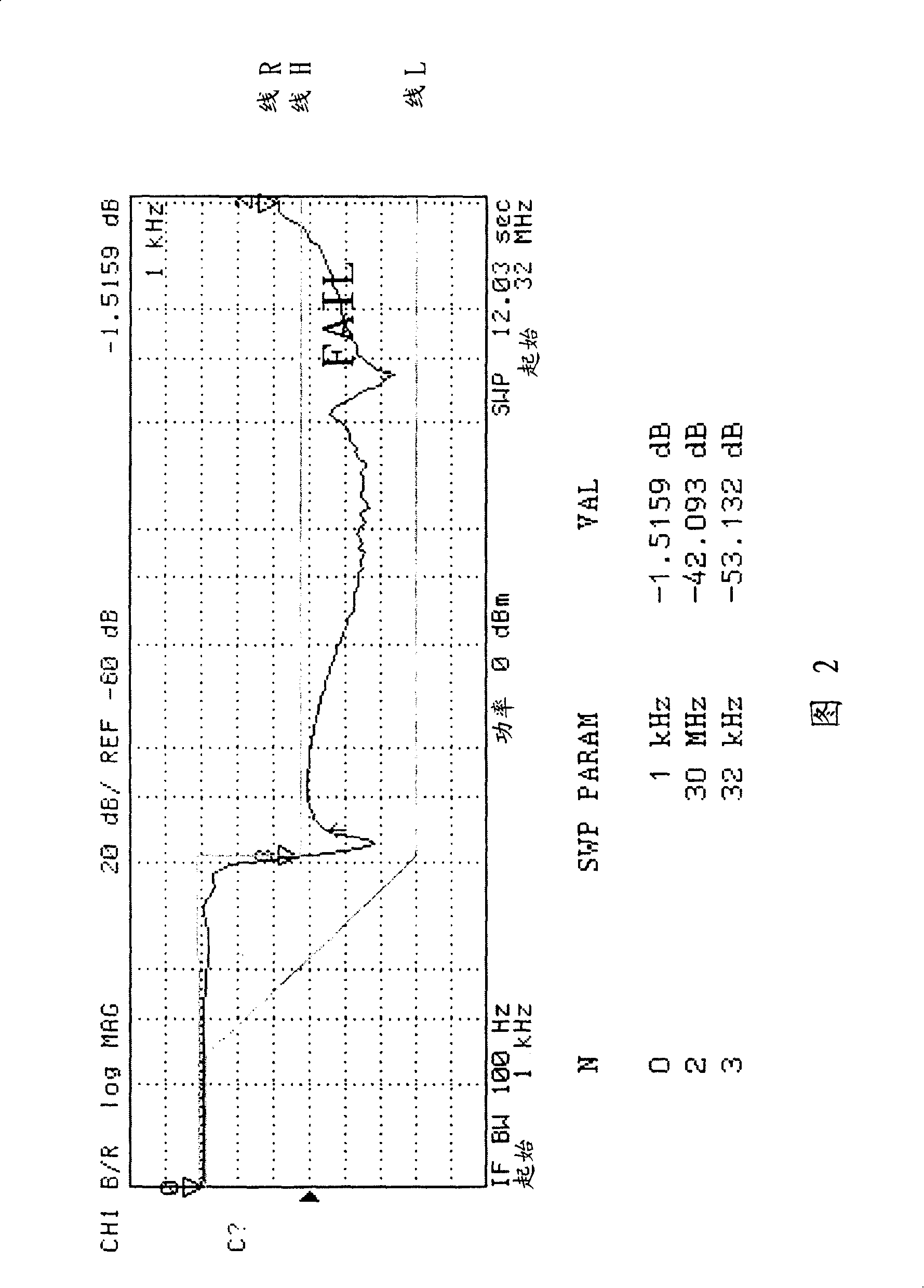
[0008] Please refer to Fig. 2, which is a frequency response diagram of the filter circuit 1 of Fig. 1, as shown in the figure, it has a first frequency response line lineH, a second frequency response line lineL, and the above-mentioned filter circuit 1 An actual frequency response line lineR generated, the first frequency response line lineH and the second frequency response line lineL are all formulated by the European Telecommunications Standards Institute (ETSI) in TS 101 952-2-1 in the VDSL2 transmission agreement The threshold value of the standard, which stipulates that when the frequency response is above 30MHZ, the noise should be below -55dB before passing the standard, but as shown in the figure, when the frequency response of the known filter circuit 1 is 30MHZ, the noise is only -42.093dB , obviously cannot be applied to the specifications formulated by the European Telecommunications Standards Agency
Furthermore, the known filter circuit 1 uses at least six inductance groups L1-L6, nine capacitors C1-C9 and four resistors R1-R4. In the industry of miniaturization and cost reduction of communication products, the performance of this known filter circuit 1 is really insufficient, so there is a need for improvement

Method used


Image

  • Wave filter circuit
  • Wave filter circuit
  • Wave filter circuit

Examples


Embodiment Construction

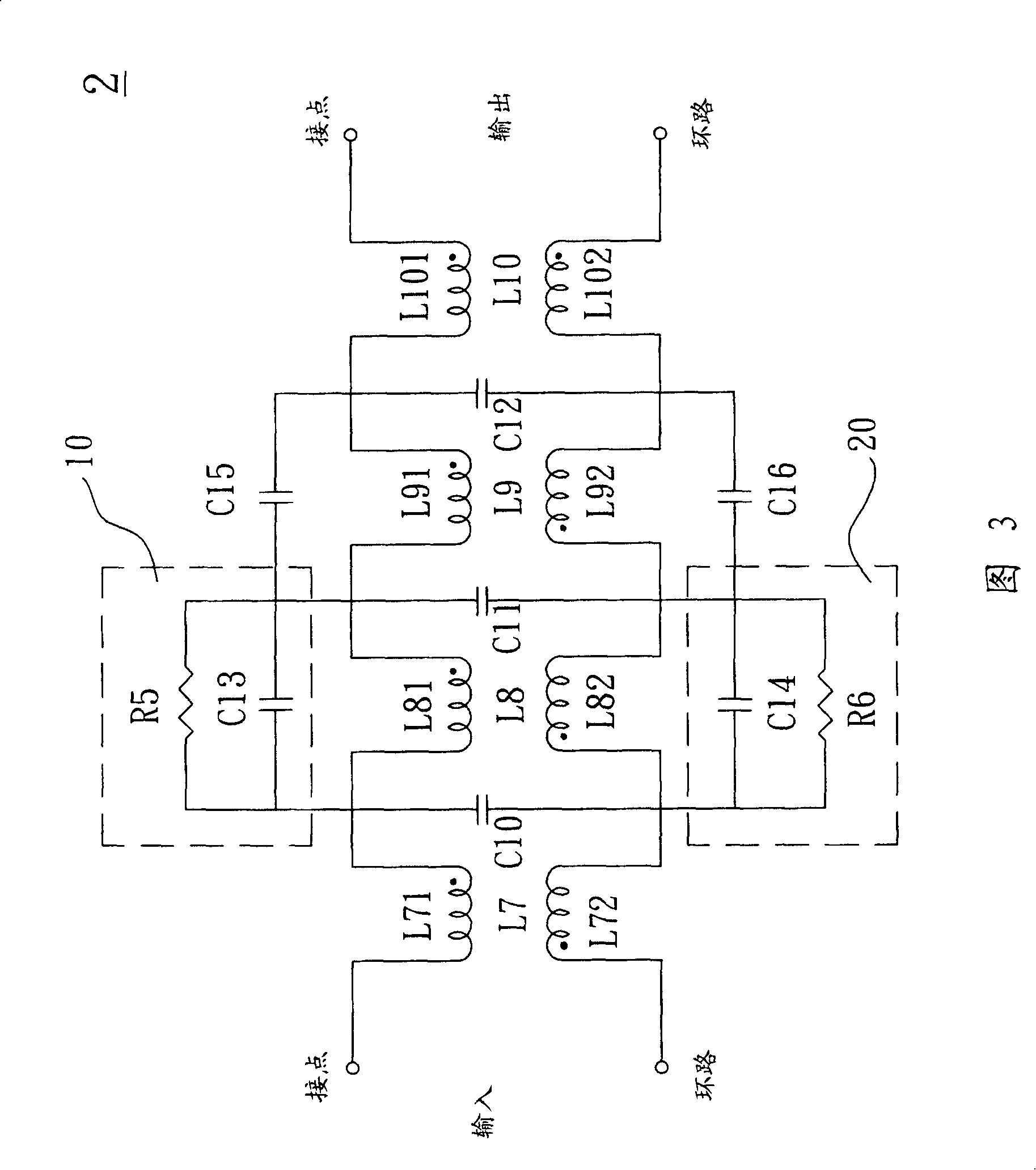
[0033] Please refer to FIG. 3 , which shows a schematic diagram of the circuit composition of the filter circuit 2 of the embodiment of the present invention; as shown in the figure, the filter circuit 2 has an input terminal input and an output terminal output, and between the input terminal input and the output terminal output The output terminal output includes a first inductance group L7, a second inductance group L8, a third inductance group L9, a fourth inductance group L10, a first resonant capacitor C10, a second resonant capacitor C11, a The third resonant capacitor C12, a first impedance matching circuit 10, a second impedance matching circuit 20, a first attenuation capacitor C15 and a second attenuation capacitor C16, wherein the plurality of inductance groups L7-L10 are electrically connected in series Between the input terminal input and the output terminal output of the filter circuit 2, each resonant capacitor C10-C12 is electrically connected between two induct...


PUM

PropertyMeasurementUnit
inductanceaaaaaaaaaa

Abstract

The invention provides a filter circuit, which is applied to the VDSL communication field. The invention consists of a plurality of inductor units, a plurality of resonant capacitors, a plurality of impedance matching circuits, and a plurality of attenuation capacitors. The inductor units are communicated in series between the input end and the output end of the filter circuit, each resonant capacitor is communicated in parallel between every two inductor units. Each of the impedance matching circuits is communicated to one of the inductor units respectively, and each of the attenuation capacitors is communicated to one of the impedance matching circuits and to one of the inductor units respectively.

Description

technical field [0001] The present invention relates to a filter circuit used in the field of communication, in particular to a filter circuit applicable to the field of VDSL (Very high bit-rate DSL) communication. Background technique [0002] Please refer to FIG. 1 , which is a schematic diagram of the circuit composition of a known filter circuit 1 used in the field of VDSL communication. The filter circuit 1 has an input terminal input and an output terminal output, and between the input terminal input and the output terminal output There are a plurality of inductor groups L1-L6, a plurality of capacitors C1-C9 and a plurality of resistors R1-R4. [0003] The input terminal input of the filter circuit 1 includes a two-pin contact, a loop (tip, ring), which is electrically connected to a communication line of a communication device (not shown in the figure), and the output terminal output also includes two pins Contacts, loops (tip, ring), which can be electrically conne...

Claims


Application Information

Patent Timeline
Patent Type & Authority Applications(China)
IPC IPC(8): H03H7/06H03H7/38H01F27/28
Inventor 李宗宪李丽娥施华盛许汉正
Owner DELTA ELECTRONICS INC
Features
  • R&D
  • Intellectual Property
  • Life Sciences
  • Materials
  • Tech Scout
  • Unparalleled Data Quality
  • Higher Quality Content
  • 60% Fewer Hallucinations
Learn More