Separating mechanism for paper

A separation mechanism and paper technology, applied in pile separation, object separation, object supply, etc., can solve problems such as paper jams, and achieve the effect of improving the operation rate

Inactive Publication Date: 2008-07-02
OKI ELECTRIC IND CO LTD
View PDF1 Cites 7 Cited by
  • Summary
  • Abstract
  • Description
  • Claims
  • Application Information

AI Technical Summary

Problems solved by technology

[0022] However, in the above-mentioned prior art, deformed paper such as paper with folded ends, paper with bent ends, paper severely crumpled by quadruple folds or double folds, etc., will not If it is detected, it will be sent to the paper conveying path with a large conveying force by the 1st conveying roller, the 2nd conveying roller, and the feed roller, etc., and will be c

Method used


Image

  • Separating mechanism for paper
  • Separating mechanism for paper
  • Separating mechanism for paper

Examples


Embodiment

[0042] First, Example 1 will be described.

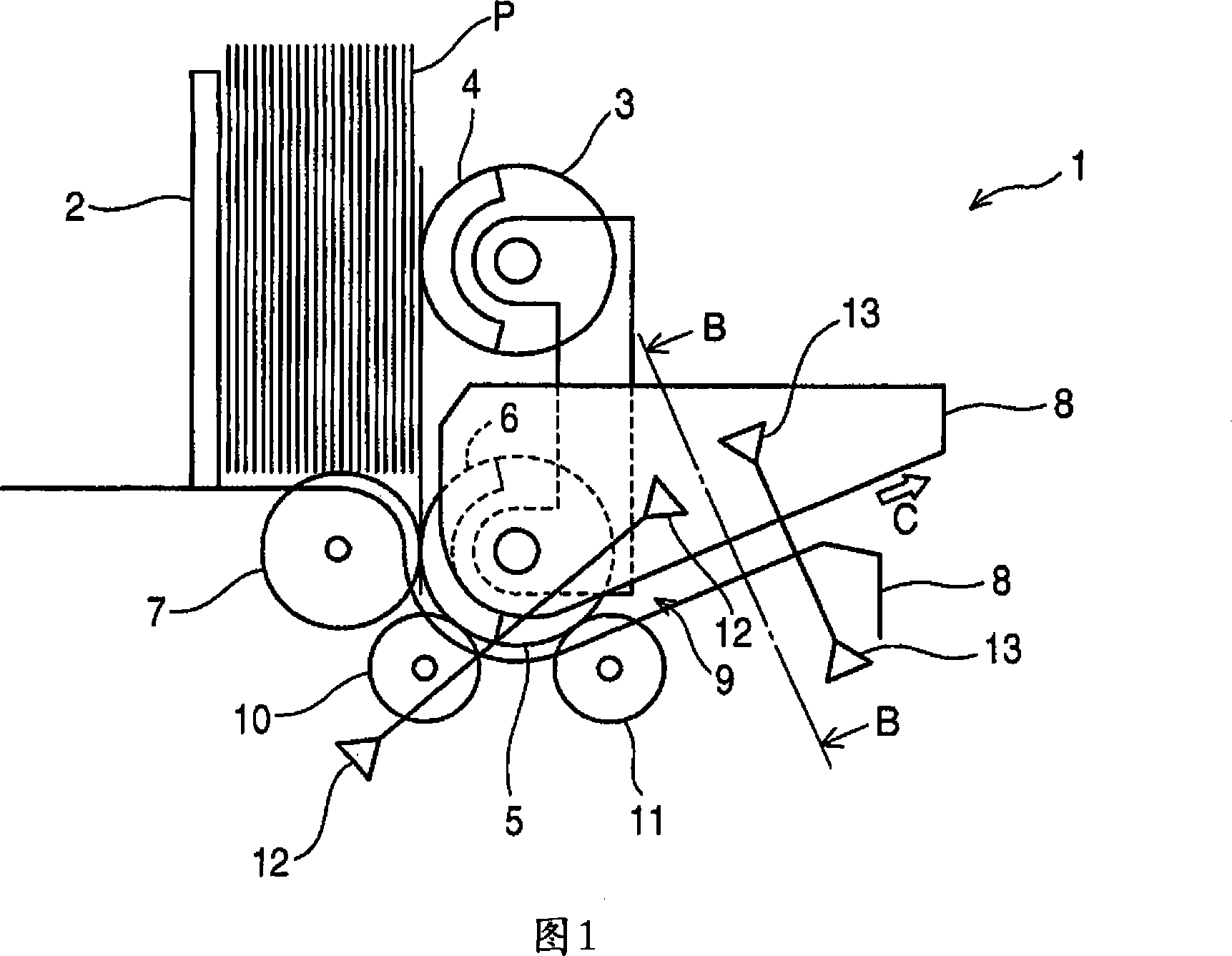
[0043] FIG. 1 is a side explanatory view showing the configuration of a sheet separation mechanism in Embodiment 1. FIG.

[0044] In FIG. 1, 1 is a paper separation mechanism, which is incorporated in cash automatic teller machines, automatic ticket issuing machines, etc., and is used to separate paper such as banknotes, currency notes, and tickets stored in the storage unit. They are separated and exported one by one, and sent to the inside of a cash automatic teller machine or the like (hereinafter referred to as "inside the machine").

[0045] Reference numeral 2 denotes a pressing plate, which is a plate-shaped member for pressing the paper sheets P stored in the paper sheet storage section. The pressing plate 2 is configured to be movable by a driving device (not shown), presses the sheets P in the sheet storage section, and abuts against a lead-out roller described later.

[0046] In addition, the paper storage unit is, for ...

Embodiment 2

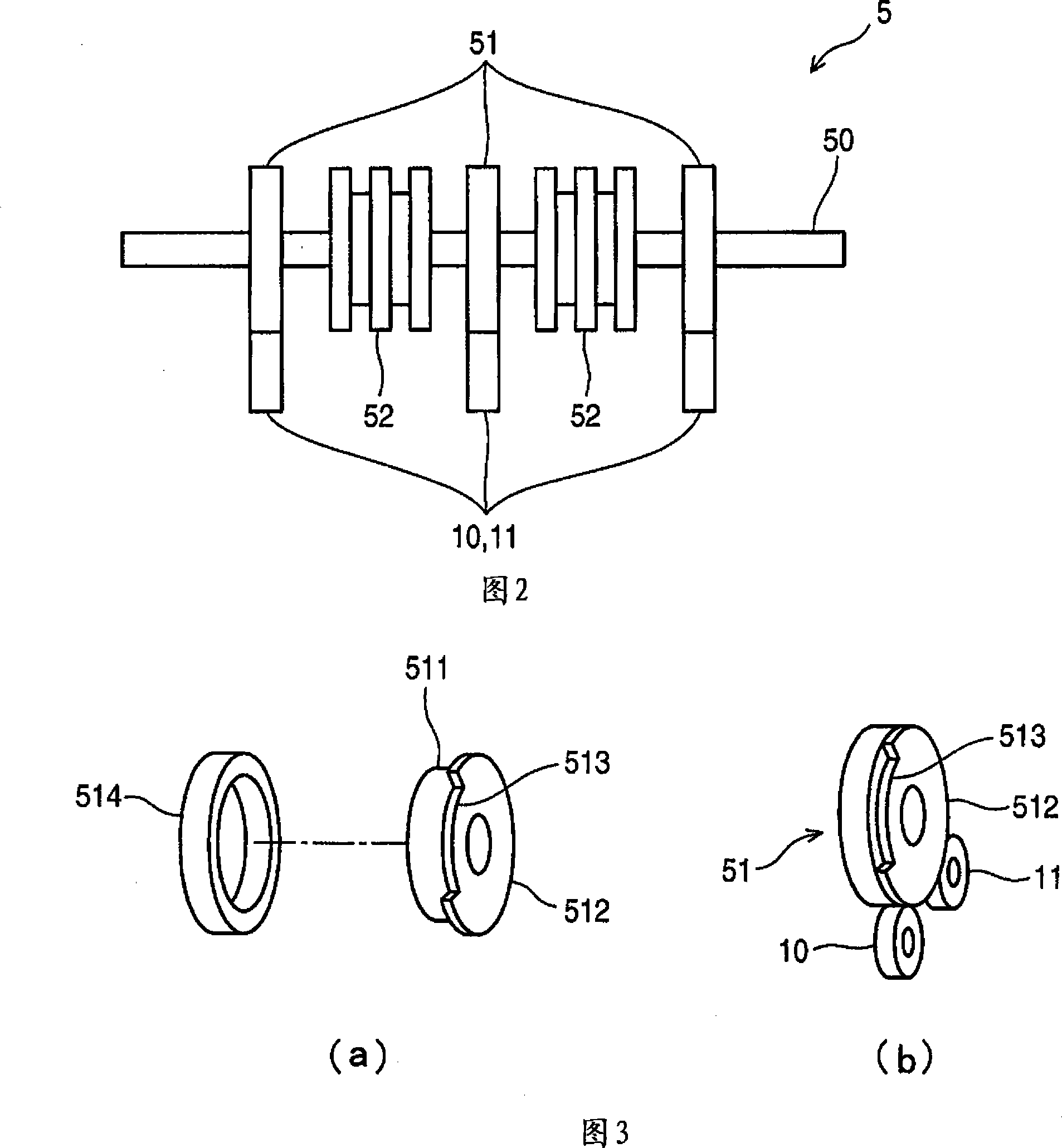
[0098] In the structure of the second embodiment, since the structure of the feed roller 5 is different from that of the first embodiment, the different structure will be described with reference to the explanatory diagram of FIG. 7 showing the structure of the feed roller in the second embodiment. .

[0099] In addition, although the structure of Example 2 is the same as that of Example 1 shown in FIG. 1, here, the transport roller hub 51 whose entire outer periphery is covered with an elastic member and has no flange will be described.

[0100] In addition, the same code|symbol is attached|subjected to the same part as the above-mentioned Example 1, and description is abbreviate|omitted.

[0101] In FIG. 7 , 70 is a feed roller rotation shaft, which is configured to be rotatable by driving means such as a motor (not shown).

[0102] 71 is a conveyance roller hub, which is attached to the feed roller rotating shaft 70, and is a roller which abuts on the 1st conveyance roller...


PUM


Abstract

The present invention provides a paper disengaging mechanism, capable of detecting distorted paper before being collected into a machine. Papers exported one by one from gate roll wheel hub (52) are holded by an elastic component of a conveying roller wheel hub (51) and a first conveying roller (10), and are transmitted to a second conveying roller (11), when the front of the paper is transmitted to the second conveying roller (11), to make the first conveying roller (10) contact to a horniness component of the conveying roller wheel hub to reduce the force for conveying paper and make the distorted paper pass through with inclined state.

Description

technical field [0001] The present invention relates to a paper separating mechanism which is assembled in a cash automatic teller machine or an automatic ticket issuing machine, etc., and can separate and export paper such as banknotes one by one. This is a paper separation mechanism that can detect deformed paper such as creases. Background technique [0002] 10 and 11, a conventional paper separation mechanism is described, FIG. 10 is a side view showing the structure of the conventional paper separation mechanism, and FIG. 11 is an explanatory diagram showing the A-A cross section of the conventional paper separation mechanism. [0003] In Fig. 10, 100 is a paper separation mechanism, which is assembled in an automatic deposit and withdrawal machine, etc., and is used to separate and export paper such as banknotes, currency notes, tickets, etc. one by one, and send them to the automatic deposit and withdrawal machine. machine, etc. (hereinafter referred to as "inside th...

Claims


Application Information

Patent Timeline
IPC IPC(8): B65H3/06B65H5/06
Inventor 高田敦近藤直人加藤光雄
Owner OKI ELECTRIC IND CO LTD
Why Eureka
Try Eureka