Tensile adjustable connection mechanism for orbit beam

A technology for connecting mechanisms and rail beams, applied in bridges, bridge parts, bridge construction, etc., can solve the problems of insufficient self-weight, difficult adjustment, and insufficient practicability, and achieves simple structure, low cost, and continuous vertical height. Infinitely adjustable effects

Inactive Publication Date: 2008-07-02
TONGJI UNIV
View PDF3 Cites 7 Cited by
  • Summary
  • Abstract
  • Description
  • Claims
  • Application Information

AI Technical Summary

Problems solved by technology

[0002] The track beam used for rail transit is placed on the substructure such as the pier through the connecting mechanism. The load of the train running at high speed, including the weight of the rail beam itself, is transmitted to the substructure through the support. The general support has Strong compressive capacity, however, when the train is running on the track, it will also generate a large upward pulling force under certain circumstances. For lighter track beams, their own weight is not enough to overcome this pulling force. Traditional track beams The supports used cannot restrain the track beams both in compression and in tension.
[0003] For example, a connection mechanism for track beams is provided in the Chinese invention patent application publication whose application number is 01126627.9 and the name is "adjustable support". The top plate of the connection mechanism is placed on the top seat, and the bottom surface of the top seat is The circular pit in the middle is just embedded in the upper ball seat, the lower ball seat is placed in the cavity of the stud, and the ball crown of the upper ball seat is placed in the matching bowl of the lower ball seat to form a ball joint. , the connection mechanism relies on the ball joint to adjust the support angle caused by the superelevation of the vertical or transverse curve of the line, and can also adjust the angle deviation c

Method used


Image

  • Tensile adjustable connection mechanism for orbit beam
  • Tensile adjustable connection mechanism for orbit beam

Examples


Embodiment Construction

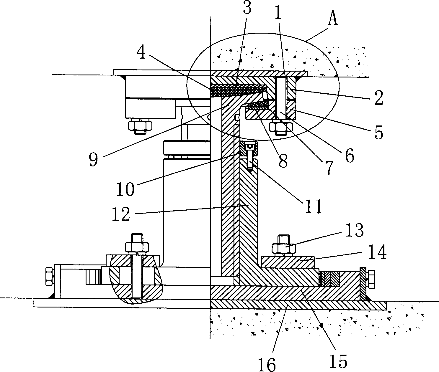
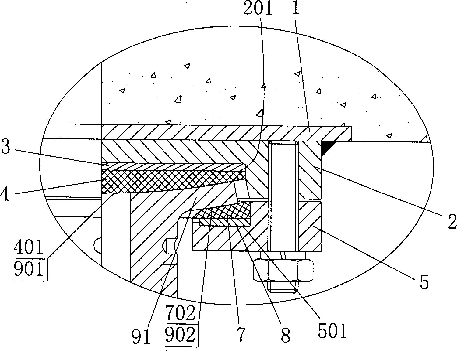
[0019] Such as figure 1 with figure 2 As shown, the upper embedded plate 1 and the lower embedded plate 16 of the track beam of the present invention are rigidly fixed on the bottom of the track beam (not shown) and the top of the pier (not shown) by pre-embedding, etc. ); the top plate 2 and the upper embedded plate 1 are fixedly connected by welding. In this embodiment, the bottom of the top plate 2 is provided with a concave cavity 201, and the first upper sliding plate 3 and the first lower sliding plate 4 are accommodated in the concave cavity. In the cavity 201; one end of the T-shaped screw rod 9 is provided with a flange 91, and its vertical cross-section becomes T-shaped, and the end face 901 of the end with the flange 91 is a concave surface, preferably a concave spherical surface, the first The lower sliding plate 4 is placed on the T-shaped screw rod 9 through its convex bottom surface 401 and the concave surface 901 of the T-shaped screw rod 9 in a relatively ro...


PUM


Abstract

The invention provides a tensile adjustable connection mechanism for railway girders, which comprises a top plate, a bolt, a fastening nut, a pedestal and a fastening screw, wherein the bolt is connected with the pedestal through a screw thread; the fastening nut is screwed on the screw thread of the bolt and is connected with the pedestal through the fastening screw; and the pedestal is connected with a lower pre-embedded plate. The mechanism also includes a lower sliding plate with one convex end face, an upper sliding plate having one concave end face, and an upper buckle plate having a support surface, wherein the other end face of the upper sliding plate is disposed on the support surface; the upper buckle plate is fixedly connected with a top plate; a flange is arranged on one end of the bolt and has a concave end face and a lower convex surface; the lower sliding plate is disposed between the top plate and the bolt through the rotatable matching between the convex surface of the upper sliding plate and the concave surface of the bolt; and the bolt is rotatably matched with the concave surface of a second upper sliding plate through the convex surface of the flange. The connection mechanism has simple structure and lower cost, and can conveniently arrange an assembly for adjusting the spatial position of the railway girder according to requirement.

Description

technical field [0001] The present invention relates to a connecting part used for installing track beams, in particular, to a tension-resistant and adjustable connecting mechanism for track beams. Background technique [0002] The track beam used for rail transit is placed on the substructure such as the pier through the connecting mechanism. The load of the train running at high speed, including the weight of the rail beam itself, is transmitted to the substructure through the support. The general support has Strong compressive capacity, however, when the train is running on the track, it will also generate a large upward pulling force under certain circumstances. For lighter track beams, their own weight is not enough to overcome this pulling force. Traditional track beams None of the bearings used can constrain the track beam both in compression and in tension. [0003] For example, a connection mechanism for track beams is provided in the Chinese invention patent appli...

Claims


Application Information

Patent Timeline
IPC IPC(8): E01D19/00
Inventor 董明钢袁亦竑万建军李文沛
Owner TONGJI UNIV
Why Eureka
Try Eureka