
Changeable magnetic disk drive holder with face mask structure

A disk drive, replaceable technology, applied in the direction of rack/frame structure, digital processing power distribution, etc., can solve the problems of inconvenient assembly and disassembly, and increased complexity of replacement operations.

Inactive Publication Date: 2008-07-02
INVENTEC CORP
View PDF0 Cites 0 Cited by
  • Summary
  • Abstract
  • Description
  • Claims
  • Application Information

AI Technical Summary

Problems solved by technology

[0005] However, the cover is fixed with multiple screws, so in terms of assembly, it must be assembled or disassembled with hand tools such as a screwdriver. Remove the cover with hand tools before installing the hard disk drive, floppy disk drive or optical drive into the originally reserved accommodation space; or the hard disk drive, floppy disk drive or optical drive is not in use If necessary, after removing the reading or storage device, the cover plate must be assembled in the opening in front of the accommodating space with hand tools; Increased complexity of dress-up actions

Method used


Image

  • Changeable magnetic disk drive holder with face mask structure
  • Changeable magnetic disk drive holder with face mask structure
  • Changeable magnetic disk drive holder with face mask structure

Examples


no. 1 example

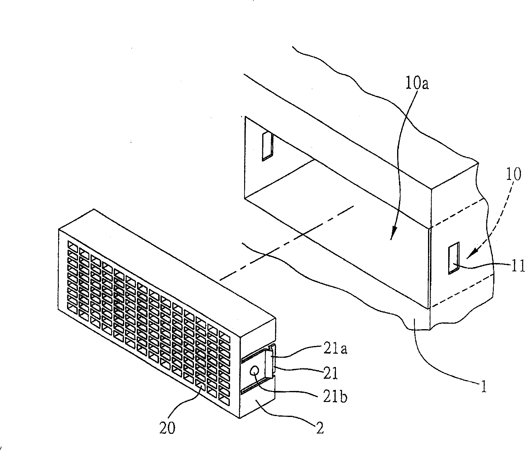
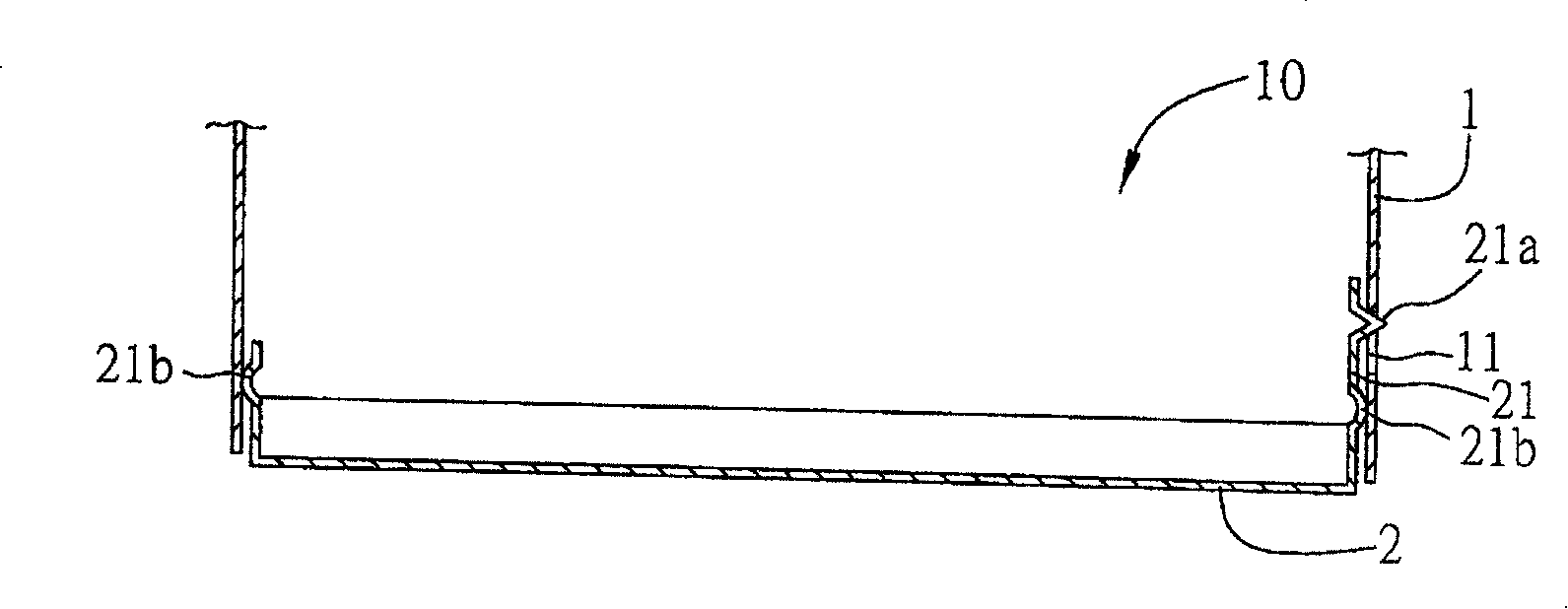
[0036] see Figure 1A and Figure 1B , is the first embodiment of the replaceable disk drive rack with mask structure of the present invention.

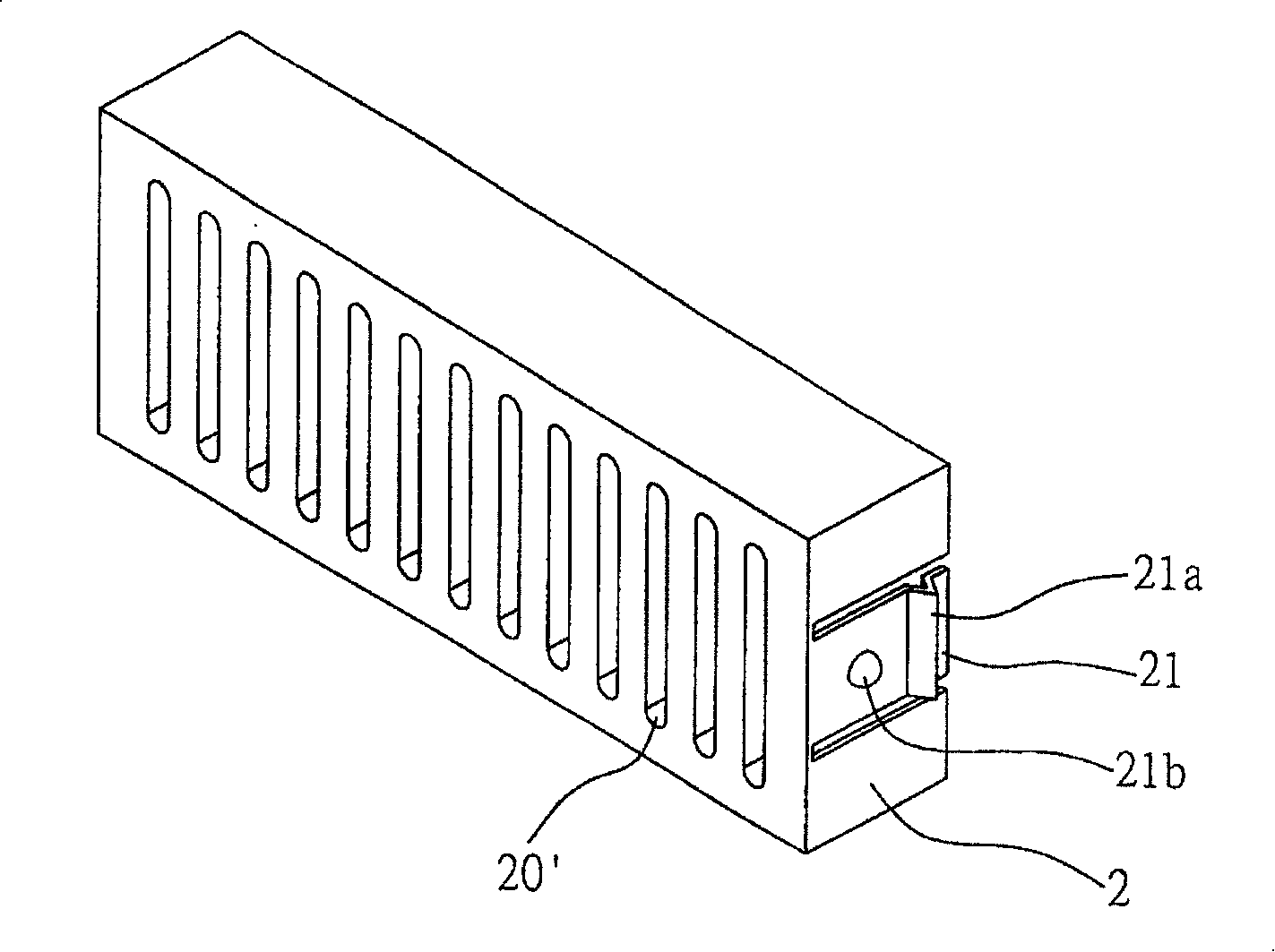
[0037] Such as Figure 1A As shown, an accommodating space 10 is provided in a disk drive rack 1 of a server, an opening 10a is provided in front of the accommodating space 10, and a button hole 11 is provided in the accommodating space 10 of the disk drive rack 1 The opening 10a in front of the accommodating space 10 is provided with a mask body 2, one side of the mask body 2 has a second joint portion, and the second joint portion has a convex portion 21a at one end and the convex portion 21a corresponds to the button hole 11, push the mask body 2 into the opening 10a in front of the accommodating space 10, and make the convex portion 21a at the end of the elastic arm 21 fit into the button hole 11, so that the mask body 2 can be assembled in the front opening 10a of the disk drive rack 1.

[0038] Such as Figure 1B As shown, t...

no. 2 example

[0045] see Figure 4A and Figure 4B , is the second embodiment of the replaceable disk drive rack with a mask structure of the present invention, which is different from the first embodiment in that the first joint part and the second joint part are an embodiment in which the mechanism is inverted.

[0046] Such as Figure 4A As shown, the first joint part in the accommodating space 10 of the disk drive rack 1 is an elastic arm 12 with a convex part 12a at the end, and the second joint part of the mask body 2 is a buttonhole 22, and the buttonhole 22 corresponds to the protrusion 12a, push the mask body 2 into the opening 10a in front of the accommodating space 10, and make the protrusion 12a at the end of the elastic arm 12 fit into the button hole 22, so that the mask The main body 2 is assembled in the front opening 10a of the disk drive rack 1; and there is a protruding point 21b on both sides of the mask body 2, through which the protruding point 21b abuts against the ...


PUM


Abstract

The invention discloses a replaceable disk driver frame with a mask structure for being assembled in the server and includes a first joint part arranged in the inner space of the disk driver frame and a mask body provided with a second joint part on one side. The second joint part is corresponding to the first joint part that the second joint part of the mask body is matched with first joint part so as to arrange the mask body into the front opening of the disk driver frame, which can avoid using hand tools to assemble or disassemble the disk driver frame panel and facilitate the replacement, avoid influencing the appearance integrity for a hollow formed in the opening of the inner space of the disk driver frame without a hard-disk driver, a soft-disk driver or a CD-ROM installed thereon, and prevent the foreign matters entering the server and influence the electrical function.

Description

technical field [0001] The invention relates to a replaceable disk drive frame with a mask structure, more specifically, a mechanism for assembling a panel into the front opening of the accommodating space in the disk drive frame. Background technique [0002] At present, electronic technology is changing with each passing day, and the assembly of various electronic devices such as computers and servers is becoming more and more sophisticated. How to effectively improve work efficiency and achieve the most economical benefits has obviously become the focus of the industry. Therefore, various electronic The assembly of each component on the device is more important in comparison; taking a server as an example, in addition to the motherboard, there are also storage devices that need to store a large amount of data, such as hard disk drives and floppy disks for reading external data. Drives and optical drives, etc.; and because the server is used for the management and storage ...

Claims


Application Information

Patent Timeline
IPC IPC(8): G06F1/18H05K7/18
Inventor 郭合文
Owner INVENTEC CORP
Learn More