Semiconductor etching equipment
An etching equipment and semiconductor technology, which is applied in the manufacture of semiconductor/solid-state devices, discharge tubes, electrical components, etc., can solve the problems of easy adhesion of reaction products, cumbersome disassembly and assembly, etc., so as to increase the efficiency of irregular maintenance and improve the adhesion state , the effect of a wide range of application prospects
- Summary
- Abstract
- Description
- Claims
- Application Information
AI Technical Summary
Problems solved by technology
Method used
Image
Examples
Embodiment 1
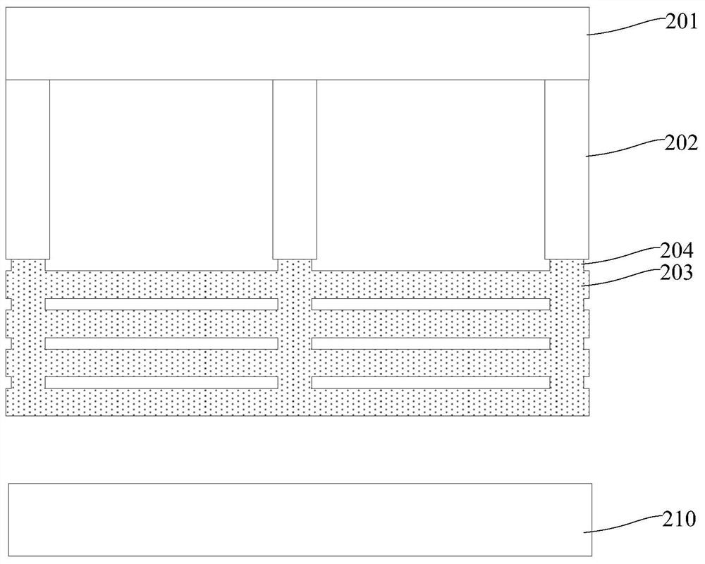
[0055] Such as Figure 3 ~ Figure 5 As shown, among them, image 3 It is shown as a schematic diagram of the assembly structure of the semiconductor etching equipment of this embodiment, Figure 4 It is shown as a schematic diagram of the disassembled structure of the semiconductor etching equipment of this embodiment, Figure 5 Shown is a cross-sectional view of the disassembled structure of the semiconductor etching device of this embodiment. This embodiment provides a semiconductor etching device, which includes: an upper electrode spray plate 201 installed in the chamber of the semiconductor etching device to provide plasma gas; an annular side wall 202; connected to The upper electrode spray plate 201; the side flow reaction element, connected to the annular side wall 202; and the lower electrode platform 210, aligned below the side flow reaction element and installed in the chamber of the semiconductor etching equipment Indoor; wherein, the lateral flow reaction eleme...
Embodiment 2
[0066] Such as Figure 6 ~ Figure 7 As shown, among them, Image 6 It is shown as a cross-sectional view of the disassembled structure of the semiconductor etching equipment, Figure 7 It is shown as a cross-sectional view of the assembled structure of the semiconductor etching equipment. This embodiment provides a semiconductor etching device, the basic structure of which is as in Embodiment 1, wherein the difference from Embodiment 1 is that the quartz ring 203 has a bonding hole 208 extending laterally outward, and the annular side wall The positioning column 205 has a clamping hole 206 corresponding to the position of the combining hole 208. After the positioning column 205 is combined with the positioning groove 207, the combining hole 208 and the clamping hole 206 are aligned with each other to limit the position. The pin 209 passes through to prevent the positioning column 205 from sliding relative to the positioning groove 207 , that is, to prevent the lateral flow r...
Embodiment 3
[0070] This embodiment provides a semiconductor etching device, the basic structure of which is the same as that of Embodiment 1, wherein the difference from Embodiment 1 is that the lower surface of the annular side wall 202 has several positioning grooves 207, and the quartz The ring 203 has several positioning posts 205 corresponding to the positioning grooves 207 , and the positioning posts 205 are combined with the positioning grooves 207 to realize the fixed connection between the quartz ring 203 and the annular side wall 202 . Further, the annular side wall 202 has a combination hole 208 extending laterally outward, and the positioning post 205 has a locking hole 206 corresponding to the position of the combination hole 208 , when the positioning post 205 and the positioning groove 207 After the combination, the combination hole 208 and the locking hole 206 are aligned with each other and connected with the limit pin 209 to prevent the positioning column 205 from sliding...
PUM
| Property | Measurement | Unit |
|---|---|---|
| thickness | aaaaa | aaaaa |
| thickness | aaaaa | aaaaa |
| diameter | aaaaa | aaaaa |
Abstract
Description
Claims
Application Information
 - R&D
- Intellectual Property
- Life Sciences
- Materials
- Tech Scout
- Unparalleled Data Quality
- Higher Quality Content
- 60% Fewer Hallucinations
Browse by: Latest US Patents, China's latest patents, Technical Efficacy Thesaurus, Application Domain, Technology Topic, Popular Technical Reports.
© 2025 PatSnap. All rights reserved.Legal|Privacy policy|Modern Slavery Act Transparency Statement|Sitemap|About US| Contact US: help@patsnap.com


