Electrical circuit breaker electromagnetical tripping apparatus

A technology of tripping device and circuit breaker, applied in the direction of protection switch operation/release mechanism, etc., to achieve the effect of simplifying manufacturing engineering

Inactive Publication Date: 2008-07-02
MITSUBISHI ELECTRIC CORP
View PDF1 Cites 4 Cited by
  • Summary
  • Abstract
  • Description
  • Claims
  • Application Information

AI Technical Summary

Problems solved by technology

[0003] However, the current value used as a reference for the above-mentioned instantaneous tripping characteristics is finely set in order to coordinate the short-time allowable characteristics of other devices such as the upper fuse of the circuit breaker with the starting current characteristics of the lower motor. Case

Method used


Image

  • Electrical circuit breaker electromagnetical tripping apparatus
  • Electrical circuit breaker electromagnetical tripping apparatus
  • Electrical circuit breaker electromagnetical tripping apparatus

Examples


Embodiment approach 1

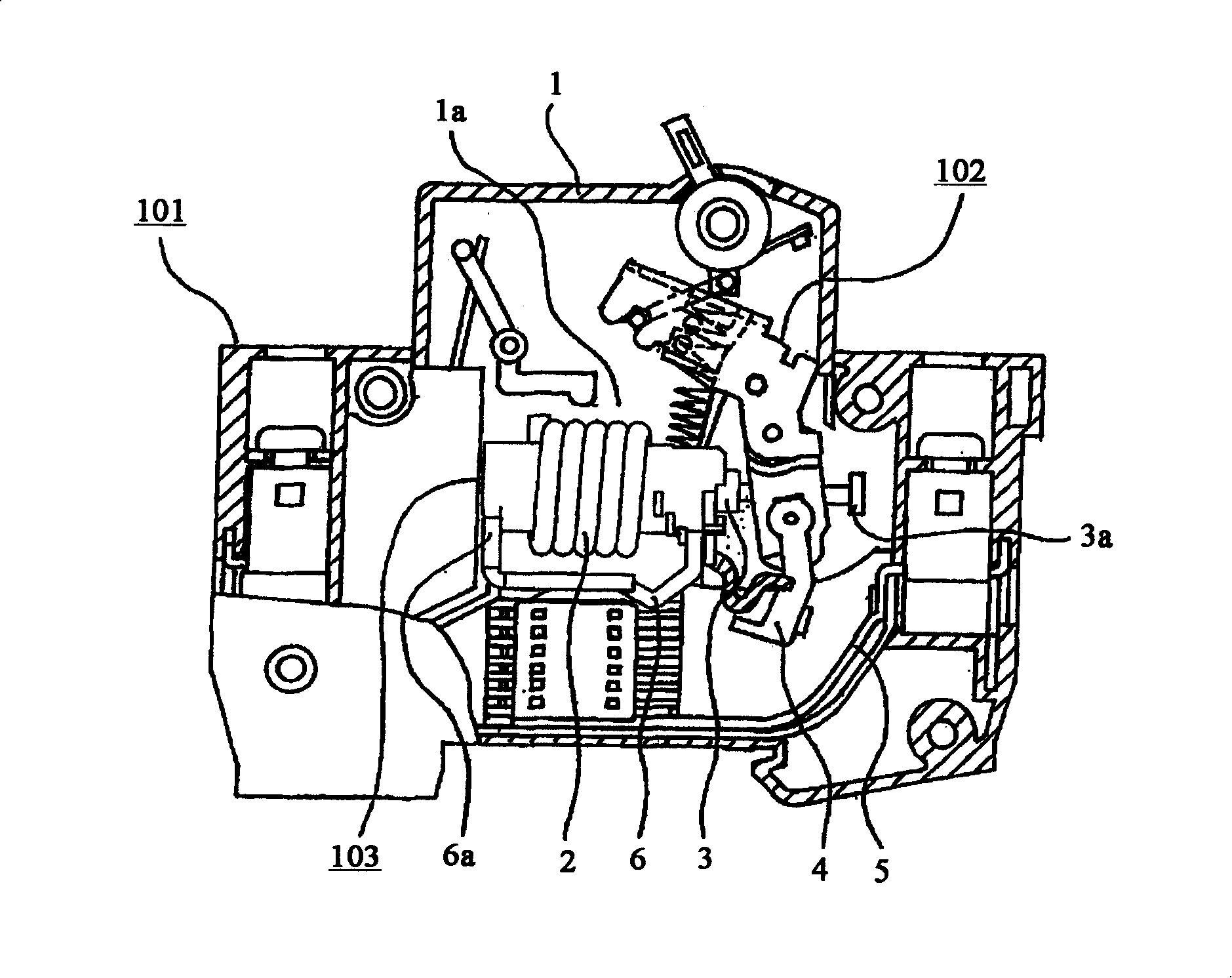
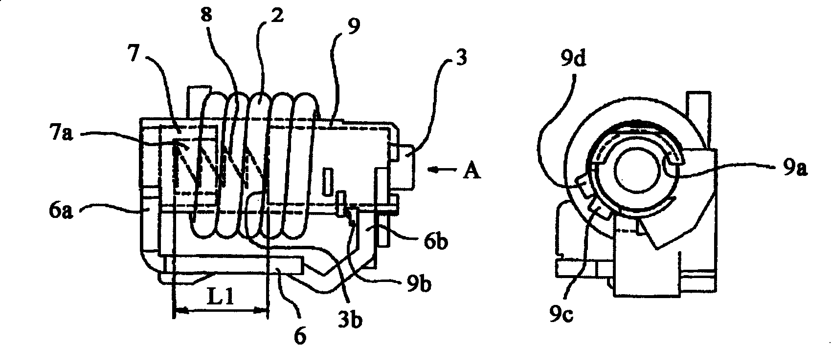
[0014] figure 1 It is a side sectional view of the circuit breaker in Embodiment 1 of the present invention, and FIG. 2 is figure 1 In the enlarged view of the electromagnetic tripping device in , part of the movable iron core is omitted, and the view seen from the A direction is also shown. In addition, in FIG. 2 , sub-numbers (a) to (c) indicate that the positions of the bobbins are different, specifically, (a) indicates D characteristics, (b) indicates C characteristics, and (c) indicates B characteristics.

[0015] figure 1 In the case 1 of the circuit breaker 101, the opening and closing mechanism 102 and the electromagnetic trip device 103 are accommodated. As is well known, when a large overcurrent flows in a circuit not shown, the The magnetic flux generated by the coil 2 moves the movable iron core 3 to the left in the figure, and the flange part 3 a provided on the movable iron core 3 operates the opening and closing mechanism part 102 to separate the movable conta...

Embodiment approach 2

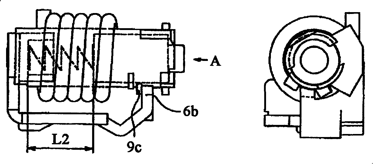
[0021] In Embodiment 1, each protrusion is formed into a substantially stepped shape, that is, there is no space between each protrusion as clearly seen in the figure viewed from the A direction. In this case, it is undeniable that there is a lack of some flexibility, that is, a margin, between the initial load and the electromagnetic force obtained from the position of each protrusion. A device having this margin will be described as Embodiment 2. also, image 3 It is a figure corresponding to FIG. 2(a) in Embodiment 2 of this invention.

[0022] exist image 3 In the figure seen from the A direction, it can be seen clearly that since the protrusions 9e to 9g are arranged with intervals between them, the difference in each initial length can be increased. Therefore, since the instantaneous trip current value may have a difference, it can be expected that high-precision coordination with upper-level or lower-level equipment can be expected on the user side. Wherein, since ...


PUM


Abstract

The invention aims at obtaining an electromagnetic tripping device for circuit breaker, which can reduce the kinds of the thrust springs and simultaneously corresponds to various instant tripping current values. The invention is made the coil rack of the guide rail of a spring between a movable core and a fixed core and can rotate with the axis of the movable core as the rotation center, and simultaneously is clamped with another vertical plate of a magnetic yoke through a ladder-shaped process arranged on the external peripheral of the coil rack so as to ensure that the initial length of the spring is changed.

Description

technical field [0001] The present invention relates to an electromagnetic trip device for regulating instantaneous trip characteristics of a circuit breaker such as a wiring circuit breaker or an earth leakage circuit breaker. Specifically, it relates to a mechanism for adjusting the instantaneous trip characteristics. Background technique [0002] The circuit breaker not only has the function of opening and closing the circuit by operating the operation panel of the circuit breaker, but also has the following important role, that is, in order to prevent the wire or wire from flowing through the current in advance. The burning of the load equipment disconnects the circuit. The so-called over-current breaking circuit usually has an inverse time characteristic, that is, the larger the current, the faster the time to complete the breaking circuit. On the other hand, when the overcurrent is large, the instantaneous tripping characteristic of the magnetic flux generated by the ...

Claims


Application Information

Patent Timeline
IPC IPC(8): H01H71/24
Inventor 池田龙典石田伸
Owner MITSUBISHI ELECTRIC CORP
Why Eureka
Try Eureka