Double-refrigerant pipe evaporator with radiator for electric refrigerator

A heat sink and evaporator technology, applied to evaporators/condensers, refrigerators, refrigeration components, etc., can solve the problems of reducing defrosting efficiency, difficult operation, and hindering the flow of cold air f1, so as to improve heat exchange efficiency, The effect of simplifying the manufacturing process and improving the defrosting efficiency

A heat sink and evaporator technology, applied to evaporators/condensers, refrigerators, refrigeration components, etc., can solve the problems of reducing defrosting efficiency, difficult operation, and hindering the flow of cold air f1, so as to improve heat exchange efficiency, The effect of simplifying the manufacturing process and improving the defrosting efficiency

CN1435613AInactive Publication Date: 2003-08-13LG ELECTRONICS (TIANJIN) APPLIANCES CO LTD

Image

  • Double-refrigerant pipe evaporator with radiator for electric refrigerator
  • Double-refrigerant pipe evaporator with radiator for electric refrigerator
  • Double-refrigerant pipe evaporator with radiator for electric refrigerator

Examples


Embodiment Construction

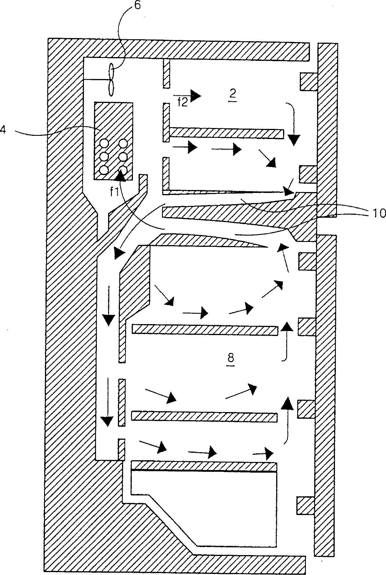
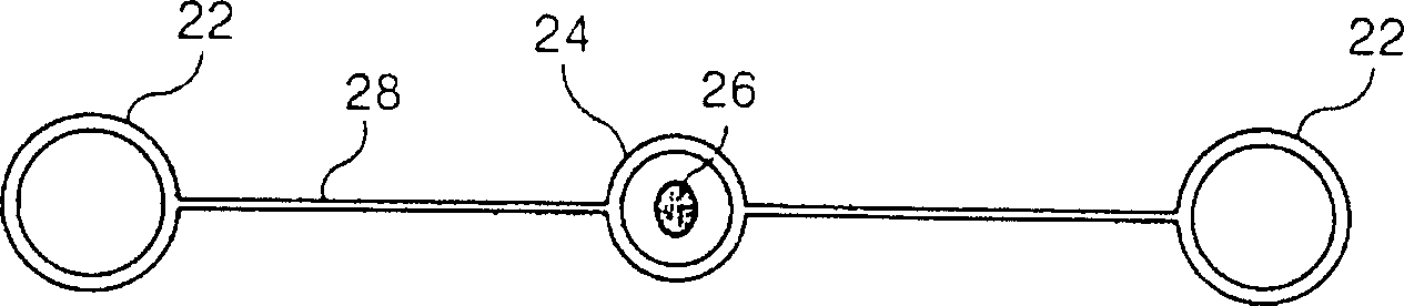
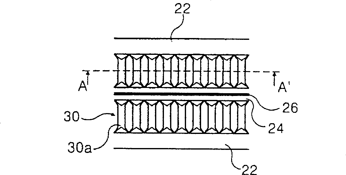
[0034] The evaporator with double refrigerant pipes and cooling fins for refrigerators includes a pair of refrigerant pipes 22 with refrigerant flowing inside, and a grid cooling fin 30 is arranged between the pair of refrigerant pipes 22 and is integrated. The pair of refrigerant pipes The tubes 22 and the louver fins 30 are bent into more than two sections. The louver fin surface 30a is provided parallel to the flow direction of the air flowing into the evaporator 4, and it is preferable to add a defrosting operation heater 64 at the lower end of the evaporator 4.

[0035] According to the present invention, between the grill fins 30 formed between the pair of refrigerant pipes 22, the space for cold air to flow is widened, thereby improving the heat exchange efficiency. Moreover, a defrosting heater 64 is additionally provided at the lower end of the evaporator 4 to improve the defrosting efficiency. And no defrosting pipe is provided between the pair of refrigerant pipes ...


PUM


Abstract

An evaporator with dual cold medium pipe and grid radiator for refrigerator is characterized by that a grid radiator is between two cold medium pipes to form a whole and said radiator and pipes are bent by more than 2 segments. A defrost heater is under the evaporator. Its advantages are high cold volume and supplying speed, high heat exchanging efficiency, and high defrost effect.

Description

technical field [0001] The invention relates to an evaporator for a refrigerator, and more particularly relates to an evaporator with double refrigerant tubes and cooling fins for a refrigerator that can improve heat exchange efficiency and fluidity. Background technique [0002] First, refer to figure 1 The heat exchange process between the refrigerant and the cold air in the refrigerator will be described as follows. [0003] Refrigerant flows into the evaporator 4 behind the freezing chamber through a compressor (not shown in the figure), a condenser (not shown in the figure) and a capillary tube (not shown in the figure). The refrigerant circulates in the refrigerator cabinet in the evaporator 4 and exchanges heat with the cold air f1 at a higher temperature. Then, the cold air f2 cooled by the above-mentioned heat exchange process is sent into the freezer compartment 2 by the blower fan 6 again. Moreover, in order to maintain a lower temperature in the refrigerator, ...

Claims


Application Information

Patent Timeline
13 Aug 2003
Publication
CN1435613A
IPC
F25B39/02
Inventors
ι‡‘δΈœεŽŸ