
Rotating LED illuminating pen

A rotary, light-emitting pen technology, applied in the field of writing pens, can solve the problems of the complex structure of the LED light-emitting pen, the complex matching of structural parts, and the increase of production and manufacturing costs, achieve ingenious structural design, ensure good conduction, and solve LED flickering. indeterminate effect

Inactive Publication Date: 2008-07-09
胡积献
View PDF1 Cites 8 Cited by
  • Summary
  • Abstract
  • Description
  • Claims
  • Application Information

AI Technical Summary

Problems solved by technology

The refill of the LED luminescent pen is controlled to move up and down relative to the pen holder through the rotating assembly arranged outside the refill, and the LED is controlled to emit light through the switch assembly arranged on the battery, that is, the refill and the refill. The light emission of the LED is controlled separately and independently, which makes it necessary to install light emitting components and other components inside the LED light pen, which makes the structure complicated and increases the manufacturing cost.
[0003] On the other hand, currently on the market, the LED luminescent pens that use push-type and stretch-type refills have many parts involved in conduction, the structure and parts are more complicated, and the cost is not low.
At present, there is no LED luminous pen that can prevent the force acting on the pen core from being transmitted to the battery, and can simultaneously control the core and LED luminescence by rotating.

Method used


Image

  • Rotating LED illuminating pen
  • Rotating LED illuminating pen
  • Rotating LED illuminating pen

Examples


Embodiment Construction

[0026] The present invention will be further described in detail below in conjunction with the accompanying drawings and embodiments.

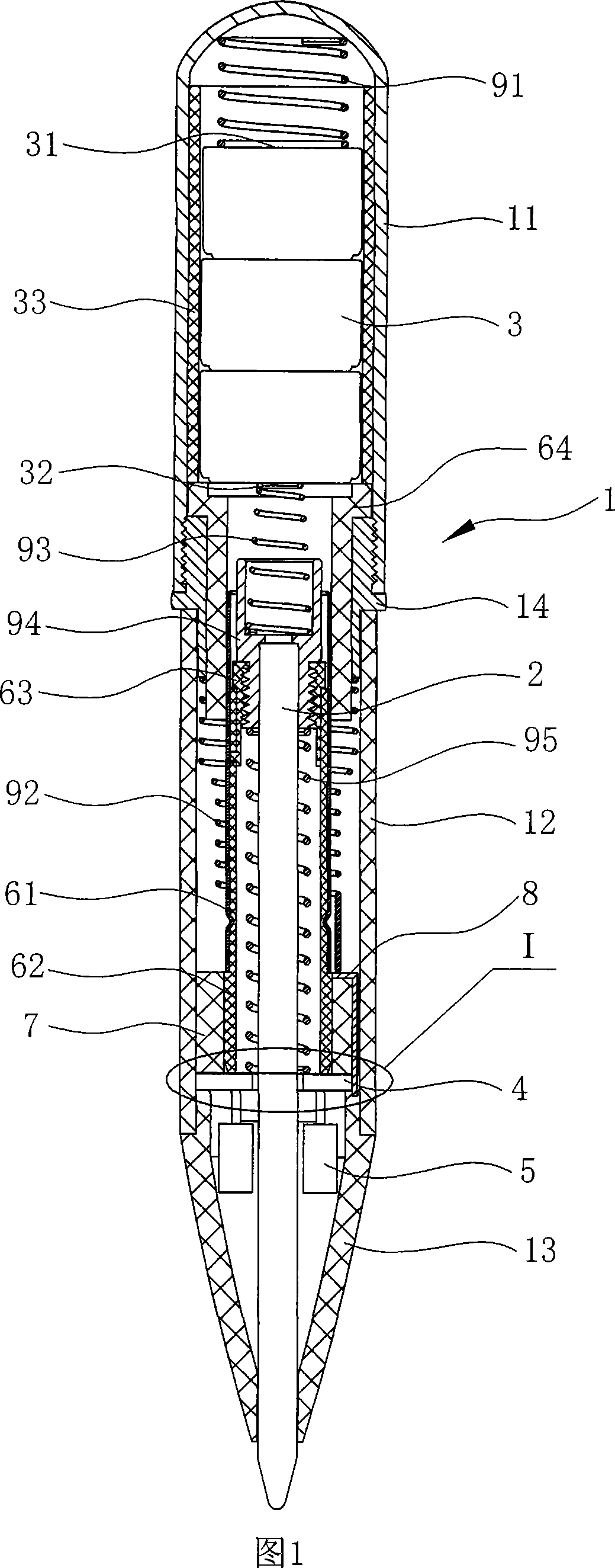
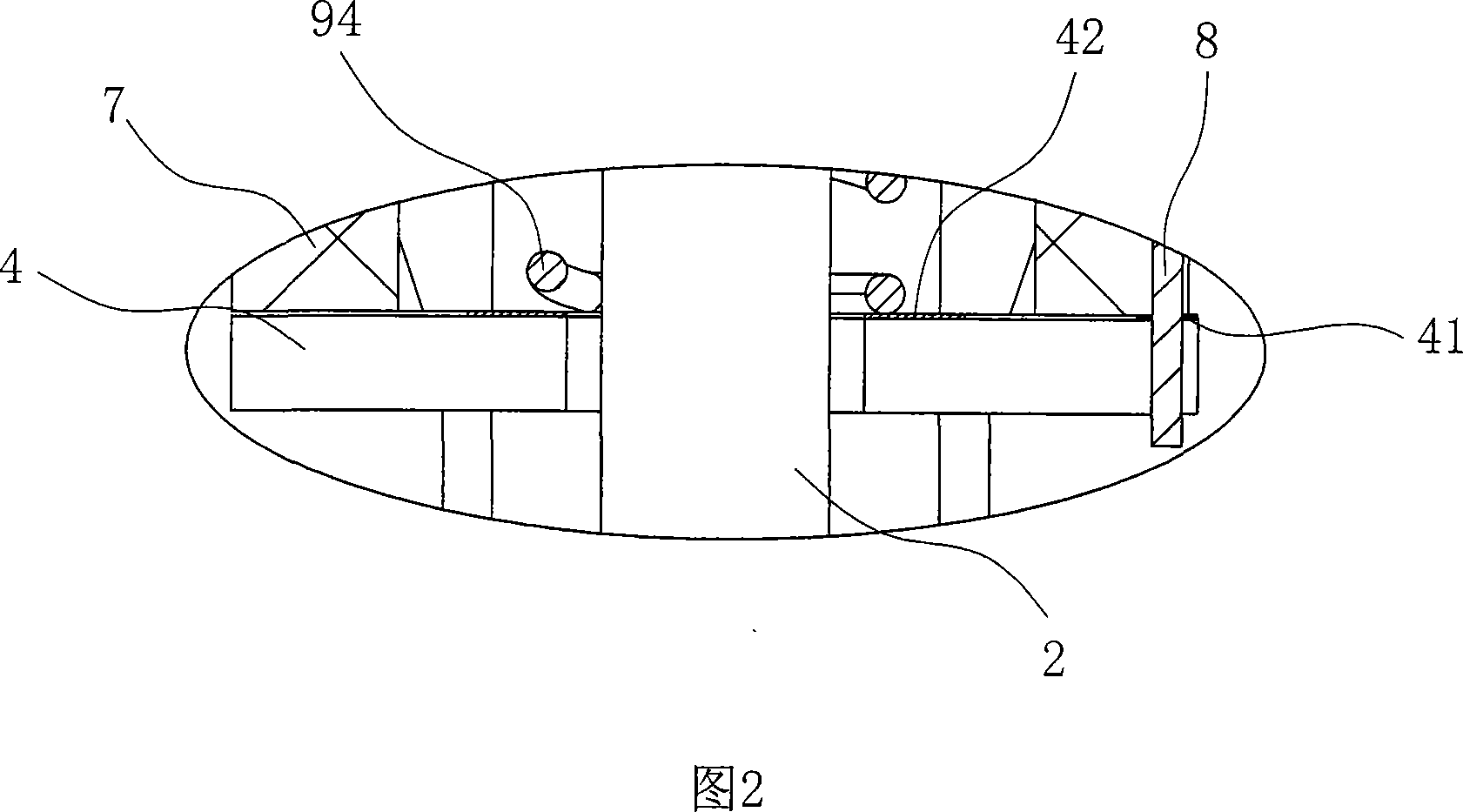
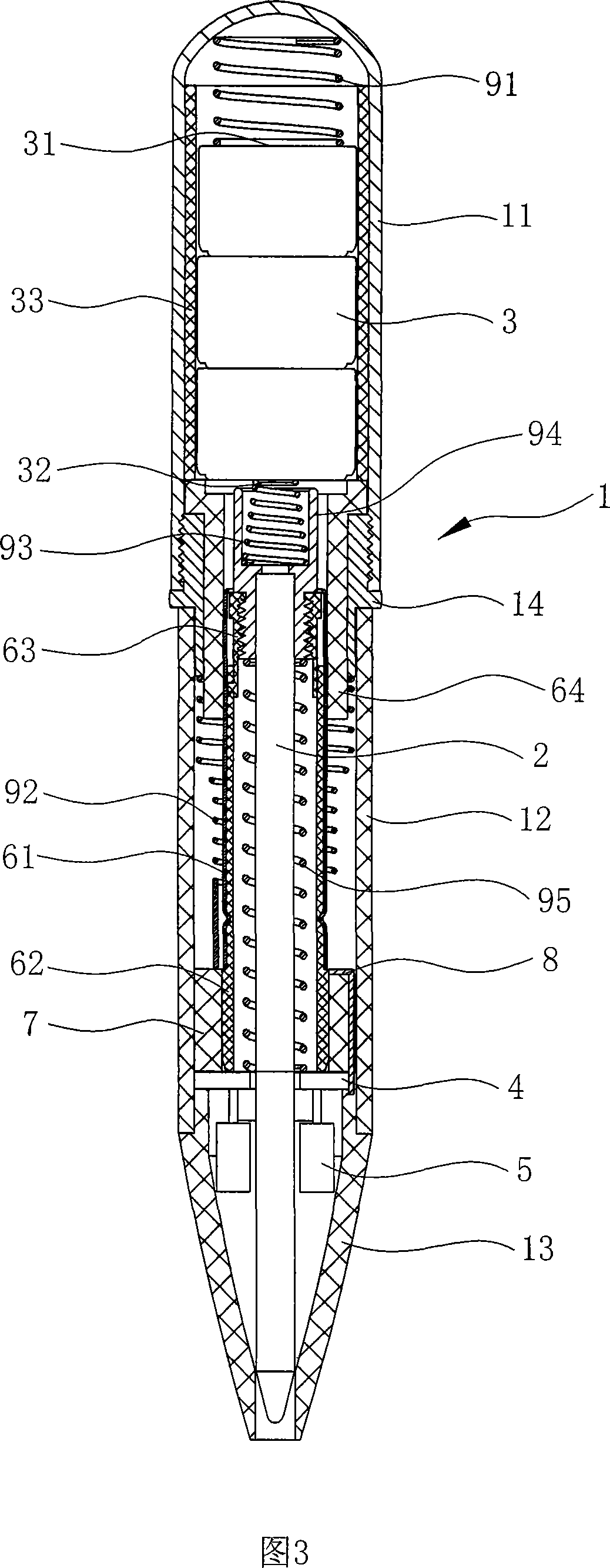
[0027] As shown in Figures 1 to 4, the rotary LED luminescent pen includes a penholder 1, a refill 2 disposed in the penholder 1, a battery 3, a light-emitting circuit board 4, and a light-emitting diode 5 connected to the light-emitting circuit board 4;

[0028] Wherein, described penholder 1 comprises upper penholder 11, middle penholder 12 and lower penholder 13, upper penholder 11 is conductive metal material, middle penholder 12 is nonmetallic material, lower penholder 13 is transparent nonmetallic material, and upper penholder 11 Can be rotated relative to the penholder 12;

[0029] The battery 3 is located in the upper penholder 11, and an insulating sleeve 33 is arranged between the battery 3 and the upper penholder 11. In this embodiment, the battery 3 is a button battery with three sections connected in series;

[0030] The light-em...


PUM


Abstract

The invention discloses a rotary LED luminescent pen, comprising a pen holder(1), a refill(2), a rotary component(6), a battery(3), a luminescent circuit board(4) and an LED(5); wherein, the upper pen holder(11) of the pen holder(1) can rotate oppositely to a central pen holder(12), the positive pole(31) of the battery(3) is connected with the positive input end(41) of the luminescent circuit board(4), the negative pole(32) of the battery(3) is connected with the negative input end(42) of the luminescent circuit board(4) through the conducting spring(95) of the negative pole and an insulating rotary sleeve(7) is arranged between a lower rotary component(62) of the rotary component(6) and the central pen holder(12); the insulating rotary sleeve(7) is provided with a metal sheet(8); the upper pen holder(11) is communicated with the metal sheet(8) through a conducting part. Compared with the prior art, the invention can realize the knock out of the refill and the luminescence of LED through the subtle match and design of the upper pen holder, the conducting part, the metal sheet and the rotary pen holder, which has the advantages of subtle and compact structure design and simpler structure.

Description

technical field [0001] The invention relates to a writing pen with an LED (light emitting diode) as a light source, in particular to a rotating LED light emitting pen. Background technique [0002] In recent years, with the rapid development of LED technology, many LED luminous pens with LED as the light source have appeared on the market. This kind of LED luminous pen has a light source, so that the original ordinary pen can be used as a miniature pen. Flashlights help to write in the dark, find items, watch watches or read letters and other purposes, so they are favored by many consumers. However, many LED light-emitting pens use the shell of the refill as a conductive part. In the LED light-emitting circuit, the top of the refill is directly in contact with one pole of the battery, and the other pole of the battery is in contact with the switch assembly. When people write with the nib of the refill, the refill is subjected to upward pressure, and this pressure is directl...

Claims


Application Information

Patent Timeline
Patent Type & Authority Applications(China)
IPC IPC(8): B43K29/10
Inventor 胡积献
Owner 胡积献
Learn More