Special-shaped drum washing machine

A drum-type washing machine and special-shaped drum technology, applied in the field of washing machines, can solve the problems of no major breakthrough in the main structure, heavy drying rotating parts, poor drying function, etc., and achieve easy transmission, small movement resistance, and improved washing efficiency. efficiency effect

Inactive Publication Date: 2008-07-09
QINGDAO UNIV OF SCI & TECH
5 Cites 11 Cited by

AI-Extracted Technical Summary

Problems solved by technology

The disadvantage of this washing machine is that the output shaft of the motor rotates through the clutch, the central gear shaft, the reversing gear, the two symmetrical gears, and the transmission gear on the back of the pulsator. The parts are heavy, the drying function is not good, and the meshing gear of the double spherical ...

Abstract

The invention relates to a washing machine, which is a special-shaped drum-type washing machine, a drum bus bar comprises three sections, the lower section is round arc, the middle section is conical, and the upper section is round ring shape, the whole section takes an ear shape, two processes which are wave wheel washing and centrifugal washing can be achieved as the changes of the speed of the drum in the process of washing. The whole machine structure comprises a rolling wheel, an outer casing, a water outlet pipe, an elastic supporting leg, a water channel, a water containing tank, a special-shaped drum, a drum cover, a water containing tank cover, an outer casing cover, a wave wheel, a motor, a belt wheel, a gear box, a bracket, a wave wheel blade and a drum shaft, a hole is arranged on the special-shaped drum, and the hole is convenient for liquid to be thrown out, and the lower portion is provided with a hole which guarantees cleaning mixture to get into the drum normally. The invention has simple structure, and the driving motion is convenient, and the invention has the characters of hand rubbing type and centrifugal type washing, which has the advantages of high utilization of mechanical energy and excellent washing effect, which saves water and electricity.

Application Domain

Technology Topic

Image

  • Special-shaped drum washing machine
  • Special-shaped drum washing machine

Examples

  • Experimental program(1)

Example Embodiment

[0023] Examples:
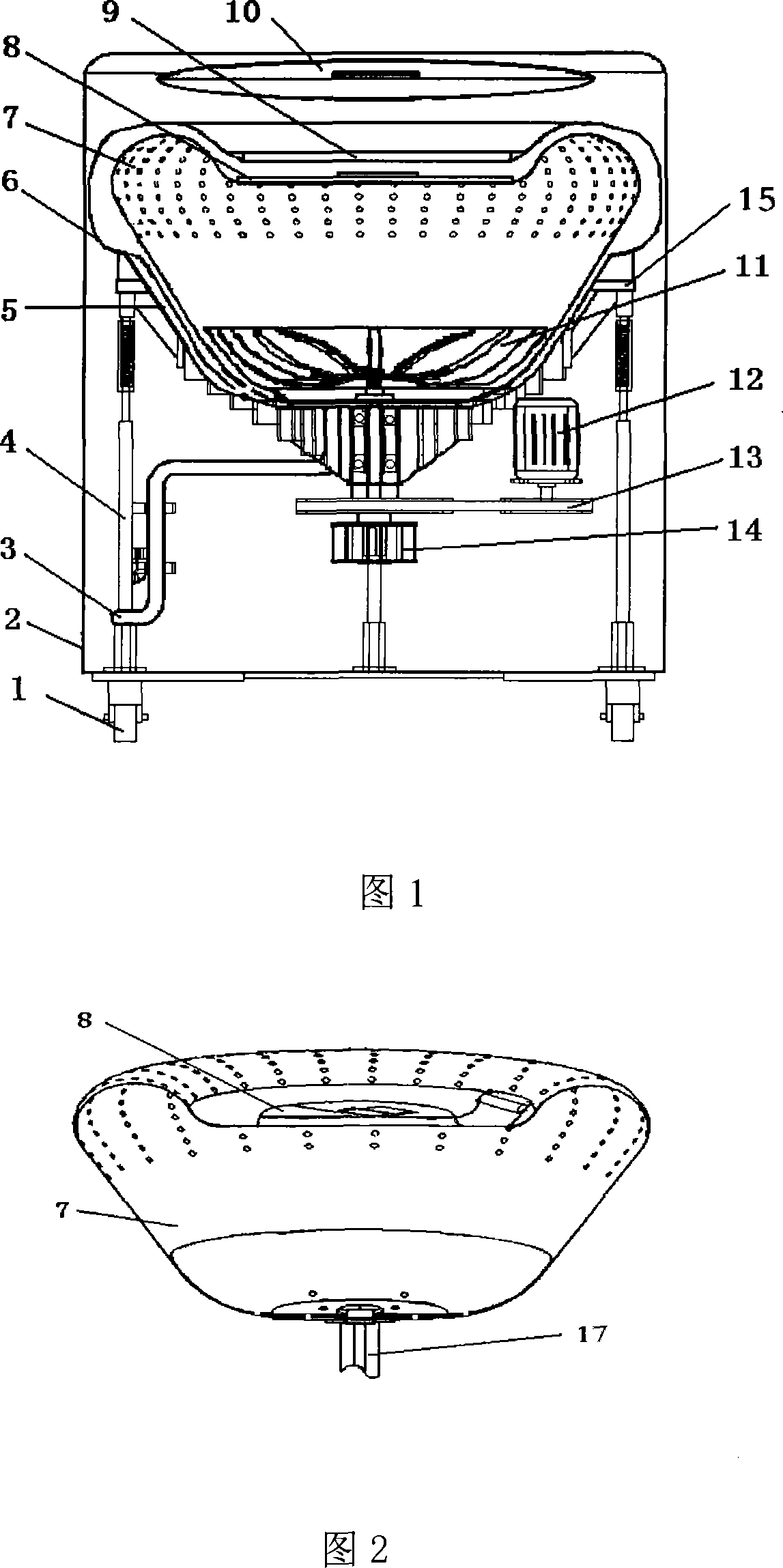
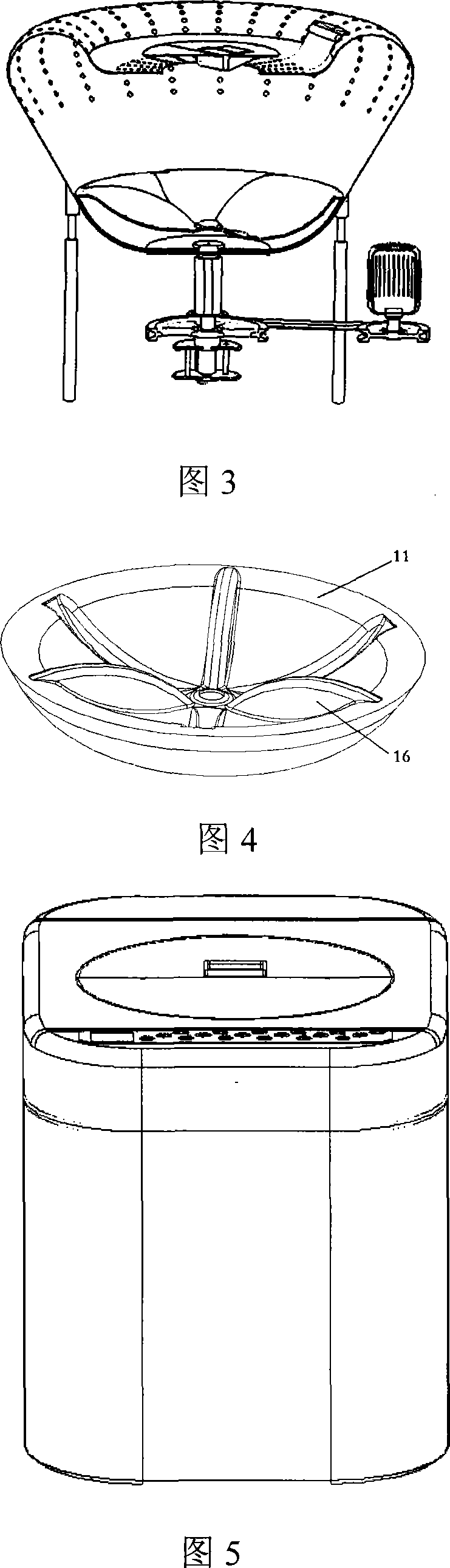
[0024] The structure of the whole machine in this embodiment includes the roller 1, the shell 2, the water outlet pipe 3, the elastic legs 4, the water channel 5, the water tank 6, the special-shaped drum 7, the drum cover 8, the water tank cover 9, the shell cover 10, and the wave wheel. 11. Motor 12, pulley 13, transmission box 14, lug 15, pulsator blade 16, and drum shaft 17.
[0025] The cross-section of the special-shaped drum 7 of this embodiment is ingot shape, and the drum bus is composed of three sections, the lower section is a semicircular arc, the middle section is a 30°-40° cone, and the upper section is an inverted arc type circular ring. Carrying clothes when running at high speed; the upper part of the drum 7 is made to facilitate the liquid to be thrown out during centrifugal washing; the bottom is also made to ensure that the washing liquid enters the drum 7 normally; the drum shaft 17 is a sleeve shaft structure, which is matched with each other. The shaft of the pulsator 11 is installed inside, and the pulsator 11 is inside the ingot-shaped drum 7; the ingot-shaped drum 7 ensures that the clothes move up and are evenly distributed during high-speed washing, and the washing liquid continuously rises along the cone and passes through the washed clothes. A centrifugal washing function is formed; the bottom of the drum 7 is equipped with a pulsator 11, the shaft of the pulsator 11 is inside the drum shaft 17, and the pulsator 11 and the special-shaped drum 7 are driven by the transmission box 14; the bottom of the whole machine is equipped with a motor 12 through a transmission belt and The belt wheel 13 is linked; the motor 12 and the transmission box 14 realize the rotation of the pulsator 11 and the special-shaped drum 7 at different washing speeds and different rotations. In the whole laundry process, a period of low-speed pulsator washing is performed first, and then the speed is increased , Into the centrifugal washing, the clothes are thrown to the upper part of the drum 7 under the action of centrifugal force, the water flows continuously upward along the cone surface, and passes through the clothes under the action of the centrifugal force, and is thrown out of the washing drum 7, realizing the combined washing of pulsator washing and centrifugal washing Mode, the drum 7 is equipped with a water tank 6, and the upper and lower water is automatically controlled by the control program design. The pulsator 11 and the drum 7 can rotate at different speeds and directions, and each stage can realize pulsator washing and centrifugal washing; In the stage, the drum rotates to achieve high-speed drying; the water tank 6 outside the drum 7 has the functions of water intake, drainage and prevention of water leakage; the water tank 6 is made of plastic material and has reinforcing ribs at the bottom; the water tank 6 carries the washing tub, water and The weight of the clothing; the upper part of the water tank 6 has a sink and a downward water ditch, which forms the water circulation during centrifugal washing; the lug 15 in the middle of the water tank 6 is connected with the elastic legs 4, and the elastic legs 4 support its full weight and Reduce vibration; the drum cover 8 is arranged on the upper part of the drum 7, one end is hinged, and the other end is a buckle structure, which is not easy to automatically open or detach; the upper part of the water tank 6 has a water tank cover 9 that opens upward, which has a sealing function. To prevent the washing liquid from leaking; the drum shaft 17 and the pulsator 11 are on the same center line, and the upper and lower bearings are matched with the shell outside the sleeve shaft. The upper and lower bearings are spaced apart, and the bearing box shell has a certain strength to ensure the high speed of the drum 7 Vibration and strength when dry; water-proof seals at both ends of the shaft prevent washing water from entering the bearing system; the shaft of the pulsator 11 and the drum shaft 17 are respectively connected to the lower transmission box 14, and the transmission box 14 realizes the difference between the pulsator 11 and the drum 7 For rotation speed and steering, there is a transmission structure with pulley 13 and motor 12 at the lower part; the washing machine shell 2 is cylindrical and made of plastic or metal plate; the shell 2 has operating keys on the panel, and movable wheels on the shell chassis.
[0026] The design structure of this embodiment is a cubic column with openings for clothing access on the top. On each layer of the cylinder, there is a circular flip-up door. The inside and outside are divided into three layers. The innermost layer is a special-shaped drum door. It is made of stainless steel; the second layer is the water tank cover 9, which is formed of plastic material to prevent leakage; the outermost layer is the housing cover 10, which is made of plastic.
[0027] When the washing machine of this embodiment works, the upper part enters water and the lower part discharges water, which is controlled by the automatic control system. When washing starts, water and detergent enter the water tank 6 together, and the washing water is about 1/3 of the clothes soaked, which meets the water consumption of the pulsator; the pulsator 11 and the special-shaped drum 7 rotate in opposite directions at the same speed. , The pulsator 11 and the drum 7 agitate the water flow to form a shock wave, and the clothes are turned and rubbed in the water wave to form a pulsator hand-rubbing laundry effect; at this time, the clothes and washing liquid are in the lower part of the drum 7, and the speed is relatively low. The medium relies on turning, kneading and water impact, while the clothes are fully soaked in the liquid, which better softens and erodes the stains inside the clothes; the reverse rotation of the pulsator 11 and the drum 7 is realized by the transmission box 14, which can be realized in one direction After rotating for many revolutions, change the direction and then rotate again; after washing the pulsator 11 for 2 to 4 minutes, the speed increases and enters the centrifugal washing stage. The clothes and washing liquid move up the cone under the action of centrifugal force, and the clothes are evenly distributed on the drum 7 In the upper arc, the washing liquid passes through the clothes and is thrown out of the drum 7, which can take away the deep stains inside the clothes; the upper space of the water tank 6 has the function of holding water, and the water thrown out by centrifugation flows into the water tank 6 along the water channel 5. At the bottom of the drum, the bottom hole of the special-shaped drum 7 enters the drum. Under the action of the pulsator 11 and the centrifugal force, the water flows continuously along the cone section to the upper clothes, thus forming a centrifugal water circulation; in order to prevent the water from being discharged outside the cone section, the irregular The cone section of the drum 7 is non-porous; the pulsator washing and centrifugal washing processes can be repeated and realized by programs. In the spin-drying stage, the liquid is first discharged from the outlet pipe 3, and the transmission box 14 can realize the synchronous rotation of the drum 7 and the pulsator 11, and after the rotation speed reaches the spin-drying speed, after a period of time, the specified dry humidity requirement is reached. Due to the realization of the two washing functions of pulsator and centrifugation, this design can achieve a higher washing ratio, save time, low wear, and at the same time save water and electricity.
[0028] The motor 12 in this embodiment is driven by a single machine. The transmission belt and pulley 13 directly drive the drum shaft 17, and drive the shaft of the pulsator 11 to rotate through the transmission box 14. The speed of the motor 12 is controlled by the washing machine program, which can realize the speed requirements of different washing processes; While transmitting power, the transmission box 14 realizes the reverse rotation and direction change of the drum 7 and the pulsator 11, and can also realize synchronous rotation.
[0029] The special-shaped drum 7 and the water container 6 of this embodiment as a support unit will be supported by four elastic legs 4, considering the weight and rotational vibration, the lugs 15 on the water container 6 should have a certain strength, and the four lugs 15 should have a certain strength. Connected with four elastic legs 4; the elastic legs 4 are inner sleeve spring structure, double-sided rubber gaskets at the bottom corner joints, connected to the chassis of the shell 2 by bolts, the elastic legs 4 ensure lowering and offsetting the roller 7 The vibration of the pulsator 11 at different speeds, especially during the centrifugal washing and spinning stage.

PUM

no PUM

Description & Claims & Application Information

We can also present the details of the Description, Claims and Application information to help users get a comprehensive understanding of the technical details of the patent, such as background art, summary of invention, brief description of drawings, description of embodiments, and other original content. On the other hand, users can also determine the specific scope of protection of the technology through the list of claims; as well as understand the changes in the life cycle of the technology with the presentation of the patent timeline. Login to view more.

Similar technology patents

Heavy metal contaminated soil washing equipment

InactiveCN111570496AImprove washing efficiencyImprove the degree of purification and the efficiency of purificationContaminated soil reclamationCleaning using liquidsMetal contaminationContaminated soils
Owner:HANGZHOU FUYANG WEIWEN ENVIRONMENTAL PROTECTION TECH CO LTD

Crude potassium repulping washing control system and control method, and crude potassium repulping washing device

ActiveCN108052129AImprove washing efficiencyWashing safetyLevel controlAlkali metal halide purificationIonMother liquor
Owner:珠海横琴华发七弦琴知识产权服务有限公司

Classification and recommendation of technical efficacy words

  • Improve washing efficiency
  • Low movement resistance

Air deflector driving mechanism and wall-hanging air conditioner

ActiveCN105402873ALow movement resistanceOrientation structure is simpleLighting and heating apparatusAir-flow control membersEngineeringGasket
Owner:GREE ELECTRIC APPLIANCES INC OF ZHUHAI

Sealing device of vacuum moving element

InactiveCN101994836ALow movement resistanceGood sealing performanceEngine sealsMotion resistanceEngineering
Owner:FOSHAN JUSHITAI POWDER METALLURGY CO LTD

Railway structure of 10000-ton movable portal crane

ActiveCN104609300ALow movement resistanceRunwaysMotion resistanceRebar
Owner:HONGHUA OFFSHORE OIL & GAS EQUIP JIANGSU
Why Eureka
Try Eureka