8k line scanning lens

A scanning lens and k-line technology, applied in the field of online scanning lens, can solve the problems of low image precision, large color difference, easy image distortion, etc., and achieve the effect of improving the detection quality

Inactive Publication Date: 2008-07-09
THE 45TH RES INST OF CETC
0 Cites 5 Cited by

AI-Extracted Technical Summary

Problems solved by technology

[0003] The purpose of the present invention is to provide a kind of 8k line scan lens, to solve the prob...

Abstract

A 8k line scan lens is characterized in that, from an object side to an image side, a first convex-concave lens, a second convex-concave lens, a doublet of a first biconvex lens and a first biconcave lens, an iris, a doublet of a second biconcave lens and a second biconvex lens, a first concave-convex lens and a second concave-convex lens are sequentially fixed in a lens barrel. The invention has the advantages of high accuracy and small aberration, and the image is unlikely to be distorted. The line scan lens with adjustable amplification rate can be applied in automatic optical detection equipment and can be matched with large-size and high-accuracy line array CCD camera.

Application Domain

Technology Topic

Image

  • 8k line scanning lens
  • 8k line scanning lens
  • 8k line scanning lens

Examples

  • Experimental program(1)

Example Embodiment

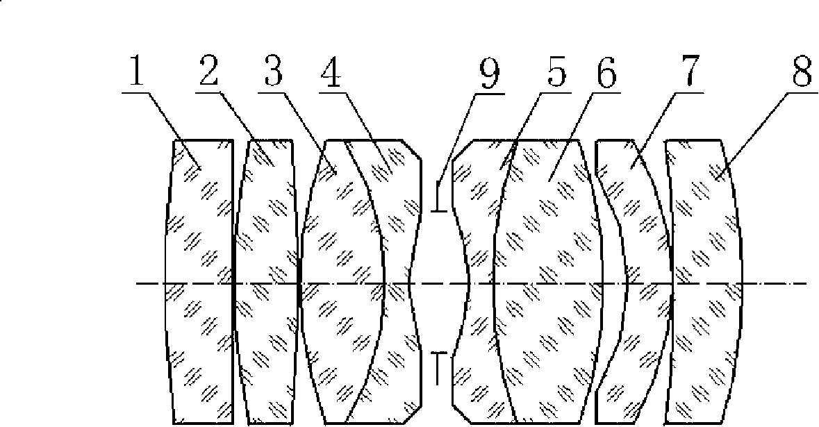
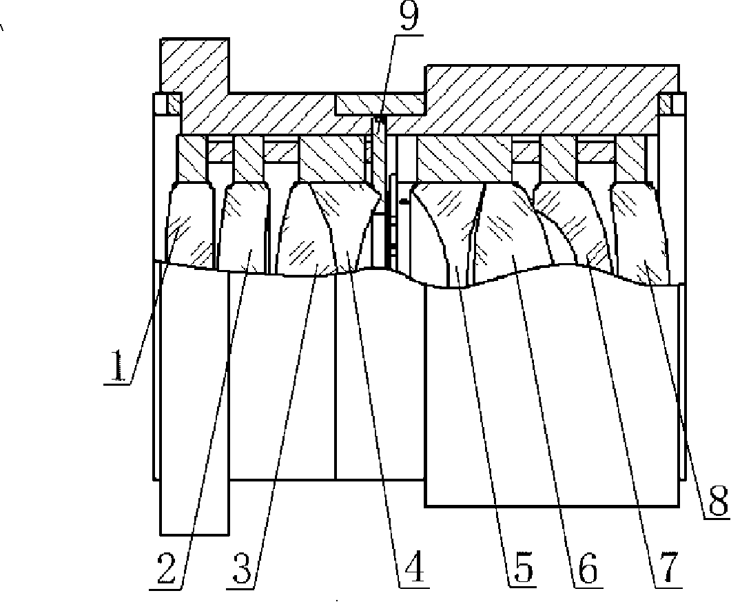
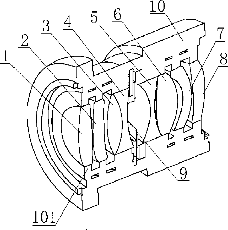
[0023] Examples see figure 1 , figure 2 , image 3 As shown, this 8k line scan lens includes a lens barrel 10 and a variable diaphragm 9 and a plurality of mirrors that are linearly combined in the lens barrel 10, and is characterized in that: from the object space to the image space, the lens barrel In 10, the first convex-concave lens 1, the second convex-concave lens 2, the first biconvex lens 3 and the glued part of the first biconcave lens 4, the variable diaphragm 9, the second biconcave lens 5 and the second biconcave lens 5 are fixed in sequence. A glued piece of convex lens 6 , a first concave-convex lens 7 , and a second concave-convex lens 8 .
[0024] A plurality of annular bosses 101 for fixing the lenses are distributed on the inner wall of the lens barrel 10 .
[0025] The working process of the present invention: the present invention is used in the visible spectrum range, and the chromatic aberration needs to be strictly corrected. At the same time, in view of the fact that the CCD camera is more sensitive to the visible light band above 600nm, the aberration of the present invention in this band also needs to be strictly controlled.
[0026] The present invention is a fixed-focus zoom lens, that is, the focal length of the lens is fixed and does not change with the adjustment of the optical path structure, but its object distance and image distance change, and its corresponding magnification also changes accordingly. The size of the square field of view is fixed, but the size of the object field of view changes with the magnification. In order to ensure the accuracy of imaging, the size of the aperture should be adjusted accordingly.
[0027] The invention takes 2X as the center, and its magnification range can meet the requirements of use within the range of 1.85 to 2.15X. The imaging part of the invention and the CCD camera are respectively fixed on two parallel guide rails, and the lens and the CCD camera are driven by the motor to move respectively. to adjust the object distance and image distance.
[0028] A toothed belt is hung on the outside of the lens aperture, and the other end is connected with a stepping motor. The rotation of the motor drives the ruler belt to adjust the size of the aperture to control the imaging accuracy and the amount of incoming light.
[0029] The following table is the relevant parameters of the present invention.
[0030]
[0031] Refer to Figure 4 for the lens transfer function curve, the abscissa: the resolution is expressed in line pairs per millimeter, and the maximum in this figure is 72 line pairs/mm. Vertical axis: imaging contrast under the corresponding resolution index. The above four indicators: TS DIFF Limit represents the diffraction limit, that is, the limit of imaging resolution. The other three represent the resolutions of the three fields of view of the image plane: 0, 20.8, and 29mm. (T represents the meridional direction (vertical axis direction), that is, the resolution in the y direction in the figure, and S represents the sagittal direction, that is, the resolution of the beam imaging in the x direction in the figure).
[0032] See Figure 5 for the field curve diagram of the lens: the displacement of each field of view on the image plane away from the paraxial focus. Abscissa: the size of the deviation. Ordinate: the height of each field of view. A total of six lines represent the field curvature in the T and S directions of the three wavelengths respectively.
[0033] See Figure 6 for the distortion curve of the lens: the imaging distortion of each field of view. Abscissa: deformation size. Ordinate: the height of the field of view at the image side. Distortion is expressed as a percentage of the ratio of the imaging deformation at each height to the ideal imaging height at that point, and the smaller the better.
[0034] See Figure 7 for vertical axis aberrations. The three sets of pictures respectively represent the aberrations in the S and T directions of the three extracted image square field heights of 0, 20.8, 29mm. Abscissa: the height of the entrance pupil, the entrance pupil is the image formed by the diaphragm on the object side, that is, the aperture of the object-side imaging beam. Vertical coordinate: the degree of deviation between the beam convergence of the imaging point and the ideal point. Indicates the distance that the light at the corresponding entrance pupil height deviates from the ideal point in the image space, the smaller the better.
[0035] See Figure 8 for the chromatic focus shift curve of the lens. Based on the wavelength of 587nm, the degree of deviation of the imaging point of the beam in the 480-640nm band.

PUM

no PUM

Description & Claims & Application Information

We can also present the details of the Description, Claims and Application information to help users get a comprehensive understanding of the technical details of the patent, such as background art, summary of invention, brief description of drawings, description of embodiments, and other original content. On the other hand, users can also determine the specific scope of protection of the technology through the list of claims; as well as understand the changes in the life cycle of the technology with the presentation of the patent timeline. Login to view more.

Similar technology patents

Throttle body negative pressure testing device

InactiveCN102121873AAdapt to testing requirementsImprove detection qualityMachine part testingType numberEngineering
Owner:SICHUAN HONGGUANG AUTO MACHINERY ELECTRONICS

Classification and recommendation of technical efficacy words

Why Eureka
Try Eureka