An exhaust blower for fluorescent lamp production

A fluorescent tube and exhaust machine technology, applied in the direction of electric tube/lamp exhaust, etc., can solve the problems of processing multiple lamp tubes, not being able to do it at the same time, and increasing the speed of lamp making

Inactive Publication Date: 2008-07-09
ZHEJIANG YANKON GROUP
View PDF0 Cites 5 Cited by
  • Summary
  • Abstract
  • Description
  • Claims
  • Application Information

AI Technical Summary

Problems solved by technology

However, the disadvantage of the circular row machine is that it can only process one lamp tube after another. Enlarging the diameter of the disk, the more lamp tubes processed at one time, the larger the diameter of the disk, which will be limited by the production site; in addition, the feature of the circular row machine is that each station is fixed at On the turntable, with the continuous rotation of the turntable, the lamp tube and the vacuum obtaining equipment need to be connected through a slide valve, and long-term continuous work will cause the vacuum degree to drop
This has become the bottleneck of improving the speed of lamp making under the premise of improving product quality

Method used


Image

  • An exhaust blower for fluorescent lamp production
  • An exhaust blower for fluorescent lamp production
  • An exhaust blower for fluorescent lamp production

Examples


Embodiment Construction

[0022] The present invention will be further described in detail below in conjunction with the accompanying drawings and embodiments.

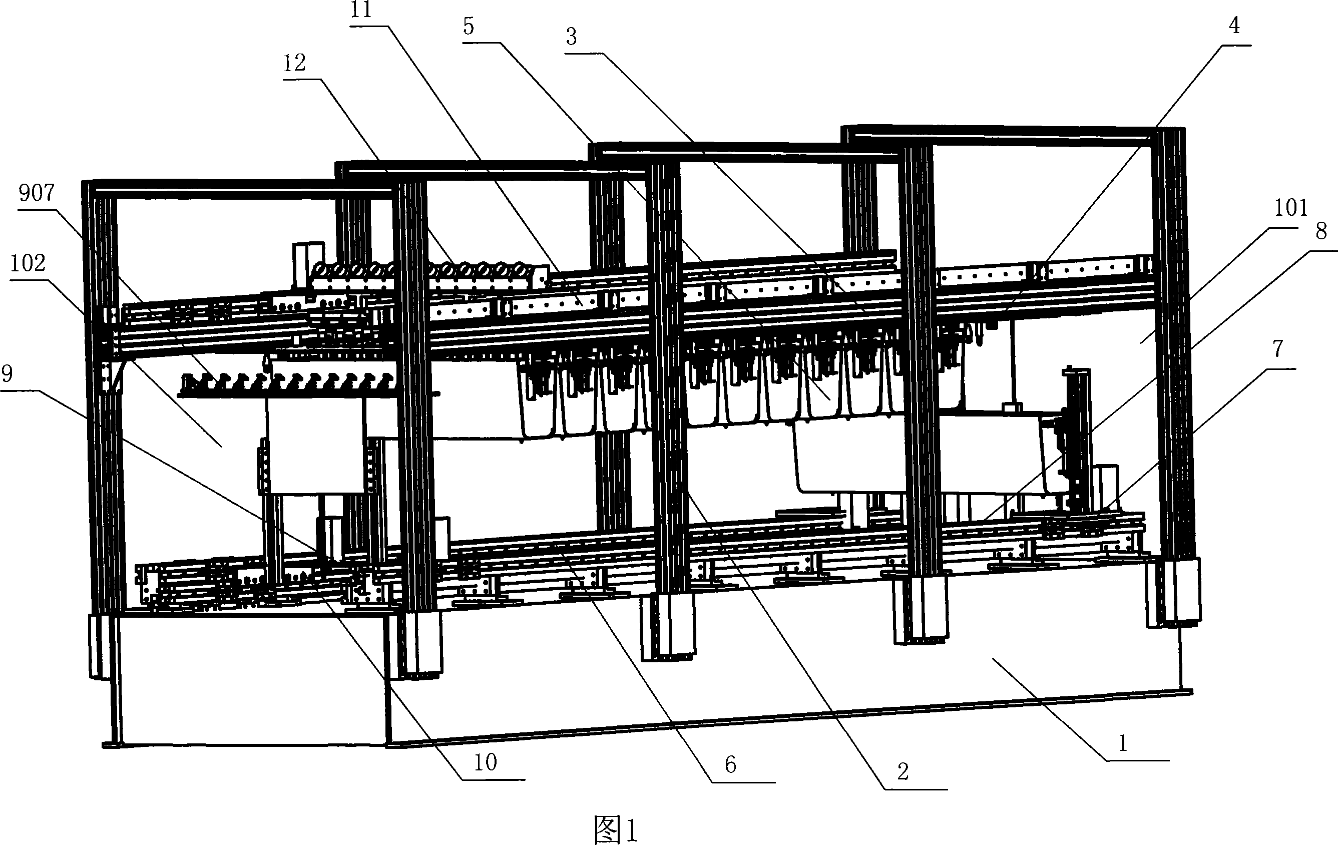
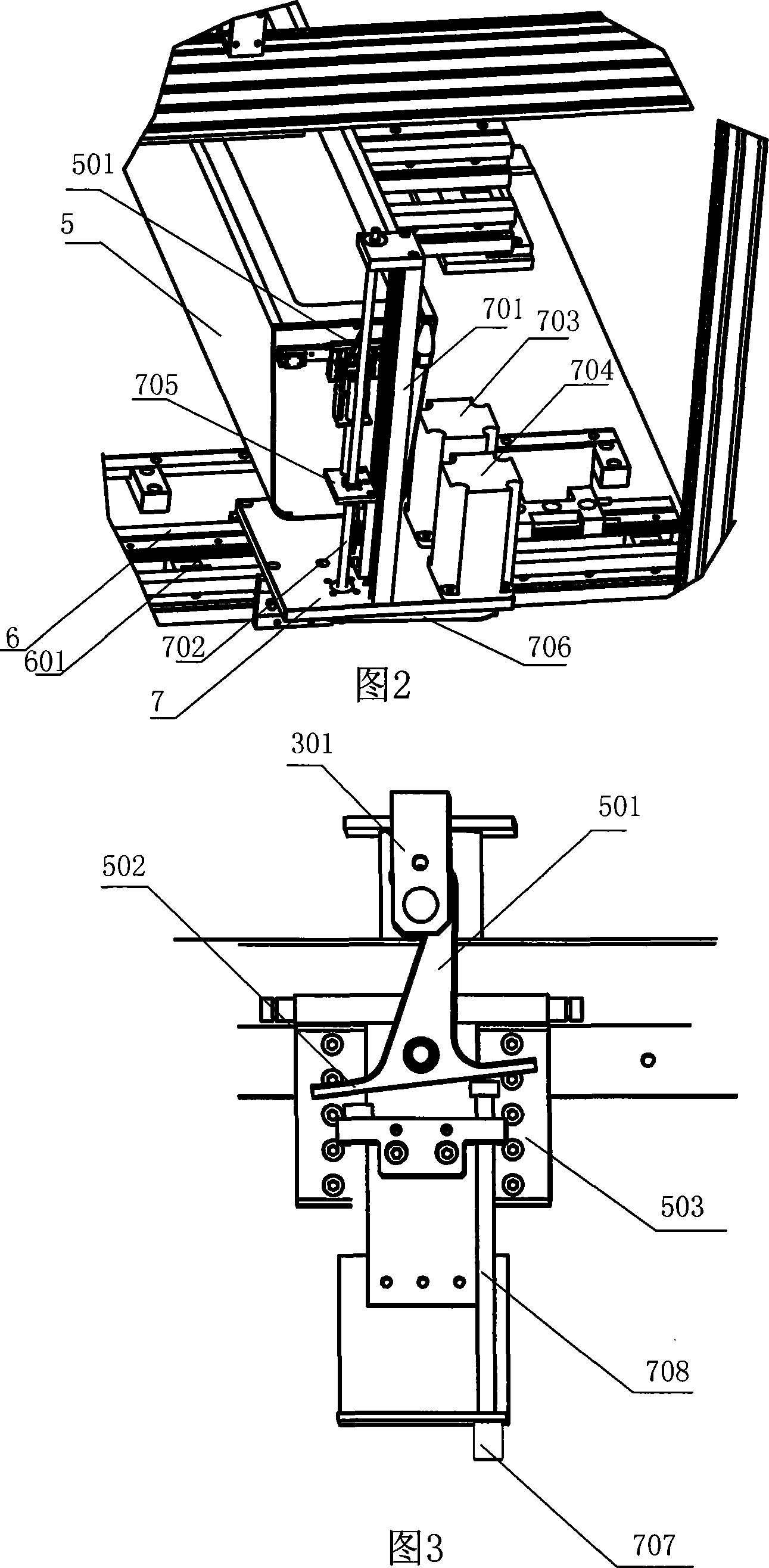
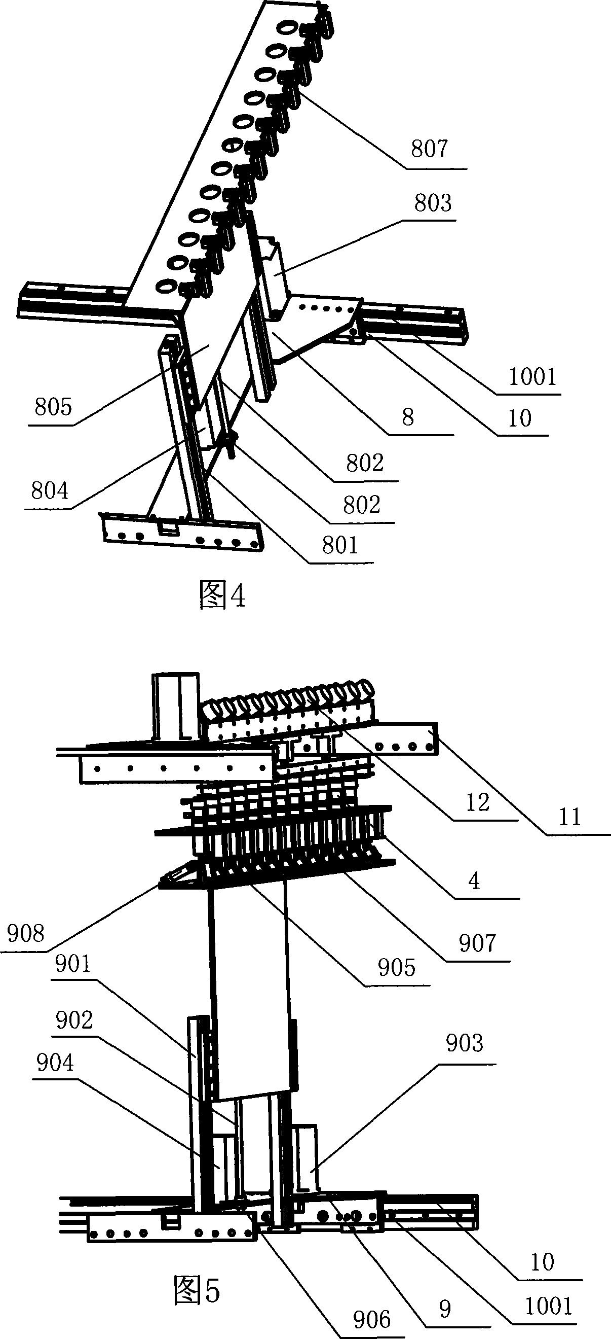
[0023]As shown in the figure, an exhaust machine for the production of fluorescent lamps includes a base 1 and a fixing frame arranged on the base 1. One end of the base 1 is an upper nozzle 101, and the other end of the base is a lower nozzle 102. The upper part of the fixed frame 2 is provided with a fixed plate 3, and the fixed plate 3 is provided with multiple rows of mercury gun groups composed of a plurality of mercury guns 4 arranged side by side, and a plurality of openings are arranged from the upper nozzle 101 to the lower nozzle 102. The oven 5 corresponding to the mercury gun group, between the upper nozzle 101 and the lower nozzle 102, two first transfer guide rails 6 and a second transfer guide rail 10 are arranged in parallel, the first transfer guide rail 6 and the second transfer guide rail 10 is arranged below the fixed plate...


PUM


Abstract

The invention discloses an exhaust machine for the production of fluorescent tubes, including a base and a fixed frame, the invention is characterized in that one end of the base is an upper pipe mouth, the other end is a lower pipe mouth, the upper part of the fixed frame is provided with a fixed board, a plurality of rows of mercury gun groups are arranged on the fixed board, each mercury gun group is composed of a plurality of mercury guns which are arranged side by side, a plurality of drying ovens which are corresponding to the mercury guns and have upward openings are arranged from the upper pipe mouth to the lower pipe mouth, drying oven fixed devices are arranged between the fixed board and the drying ovens, a first transmission guide track group which is arranged below the fixed board and a second transmission guide track group which is arranged above the fixed board are arranged between the upper pipe mouth and the lower pipe mouth; a drying oven ascending and descending device, an upper pipe device and a lower pipe device which can move along the first transmission guide track group are arranged on the first transmission guide track group, the second transmission guide track group is provided with a mercury filling device which can move along the second transmission guide track group, and the invention has the advantage that the exhaust machine can simultaneously realize the continuous exhaust processing of a plurality of lamp tubes under the situation of non-mobile processing working position.

Description

technical field [0001] The invention relates to a fluorescent lamp production equipment, in particular to an exhaust machine for the production of fluorescent lamp tubes. Background technique [0002] One of the production equipment that needs to be used in the production process of fluorescent lamps is the exhaust machine. The existing exhaust machines are mainly circular row machines. During operation, the upper tube mechanism puts the bridged lamp tubes on the circular row machine For each station, the processed lamp tubes are sequentially sent to each position on the circular row machine through the turntable set on the circular row machine for processing, and the exhaust operation of each lamp tube can be completed continuously. However, the disadvantage of the circular row machine is that it can only process one lamp tube after another. Enlarging the diameter of the disk, the more lamp tubes processed at one time, the larger the diameter of the disk, which will be lim...

Claims


Application Information

Patent Timeline
Patent Type & Authority Applications(China)
IPC IPC(8): H01J9/385
Inventor 茅建龙
Owner ZHEJIANG YANKON GROUP
Why Eureka
Try Eureka