A monocycle feedforward switch control circuit

A switching control circuit, single-cycle technology, applied in circuits, control/regulation systems, electrical components, etc., can solve the adverse effects of the R0 switching power supply circuit that cannot control the load well, the flexibility is not high, and the load disturbance single cycle cannot be realized. Period control and other issues, to achieve the effect of good resistance to power disturbance, high flexibility, and good resistance to load disturbance

Inactive Publication Date: 2010-06-02
HUAZHONG UNIV OF SCI & TECH
View PDF7 Cites 0 Cited by
  • Summary
  • Abstract
  • Description
  • Claims
  • Application Information

AI Technical Summary

Problems solved by technology

However, this control mode cannot well suppress the adverse effects of the output load disturbance on the switching power supply circuit in the application of the switching power supply circuit.
Take the Buck structure as an example, such as figure 2 As shown in the connection into a nonlinear control loop, the figure 1 The input terminal X(t)11 of the shown control circuit is connected to the power supply voltage VIN, the output terminal Y(t)12 is connected to the node 28, and the voltage of the node 28 is sampled so that the average value in a single cycle is equal to Vref13, because The disturbance of the power supply voltage VIN can be instantly fed back as the change of the voltage at node 28, so the influence of the power supply voltage disturbance on the output VOUT can be effectively controlled, but the disturbance of the load R0 cannot be fed back to the node 28 immediately, and it usually takes several cycles , so the single-cycle control of the load disturbance cannot be realized, and the adverse effects of the disturbance of the load R0 on the switching power supply circuit cannot be well controlled
In addition, this kind of single-cycle nonlinear control is different for different topological structures of switching power supplies, and the integration circuit for the feedback value is different in the application process, and the flexibility is not high.

Method used


Image

  • A monocycle feedforward switch control circuit
  • A monocycle feedforward switch control circuit
  • A monocycle feedforward switch control circuit

Examples


Embodiment Construction

[0019] Below in conjunction with accompanying drawing and example the present invention is described in further detail.

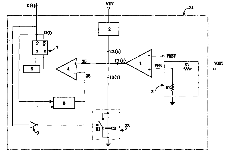
[0020] Such as image 3 As shown, the single-cycle feedforward switch control circuit of the present invention includes the following parts: transconductance amplifier 1, voltage-current conversion circuit 2, resistor divider network 3, comparator 4, controllable voltage threshold module 5, clock 6, RS Flip-flop 7, NOT gate 9, integral network 33.

[0021] The resistor divider network 3 is composed of resistors R1 and R2 in series, and samples the output voltage VOUT of the switching power supply. The output voltage VOUT of the switching power supply is divided by the resistors R1 and R2, and the output voltage signal VFB is connected to the positive terminal of the transconductance amplifier 1, and the negative terminal of the transconductance amplifier 1 is connected to the reference reference VREF. The voltage-current conversion circuit 2 samples the p...


PUM


Abstract

The invention discloses a single period feed forward switch control circuit, comprising a trans-conductance amplifier, a comparator, a clock, an RS trigger, an integrating network, a voltage and current converting circuit, a controllable voltage threshold module, a not gate and a resistor dividing network. In a switch period, an output signal of the switch circuit is integrated, and produces a feedback signal which represents the mean of the output signal in a switch period. The feedback signal and a reference voltage are compared by the comparator, and when the value of the feedback signal isequal to that of the reference voltage, the comparator produces a switch control signal to regulate the duty ratio of the switch circuit so as to stabilize the output voltage. A feed forward path which increases the sampling input voltage is added to the feedback control circuit. In the mode, the control circuit can sample both the output signal and the input signal at the same time and change the duty ratio of the switch circuit according to the sampling signal. The invention can enhance the disturbance rejection and optimize the dynamic performance of the switch power output.

Description

technical field [0001] The invention belongs to integrated circuit chip technology, and specifically relates to a single-cycle feedforward switch control circuit, which is applied to switching power supply circuits and signal processing, and is especially suitable for switching and regulating circuits from direct current (DC) to direct current (DC). It can enhance the anti-disturbance and dynamic characteristics of the switching power supply output. Background technique [0002] Switching power supply is a nonlinear dynamic system. It is difficult to achieve the ideal control effect when the power system is subjected to large parameter perturbation and nonlinearity by using the traditional linear feedback control method. Appropriate pulse nonlinear control can optimize the dynamic characteristics of switching power supply and reduce the influence of input power supply and output load on the output of switching power supply. [0003] U.S. Patents U.S.752,068 and U.S.5,278,49...

Claims


Application Information

Patent Timeline
Patent Type & Authority Patents(China)
IPC IPC(8): H02M1/08H02M3/156H01L25/00H01L27/00
Inventor 邹雪城刘政林陈晓飞李思臻甘泉张浩张涛吴俊
Owner HUAZHONG UNIV OF SCI & TECH
Why Eureka
Try Eureka