

Die for injection compression molding
A technology of compression molding and mould, applied in the direction of coating, etc., can solve the problem of insufficient stability of the position
- Summary
- Abstract
- Description
- Claims
- Application Information
AI Technical Summary
Problems solved by technology
Method used
Image

Examples
no. 1 Embodiment approach
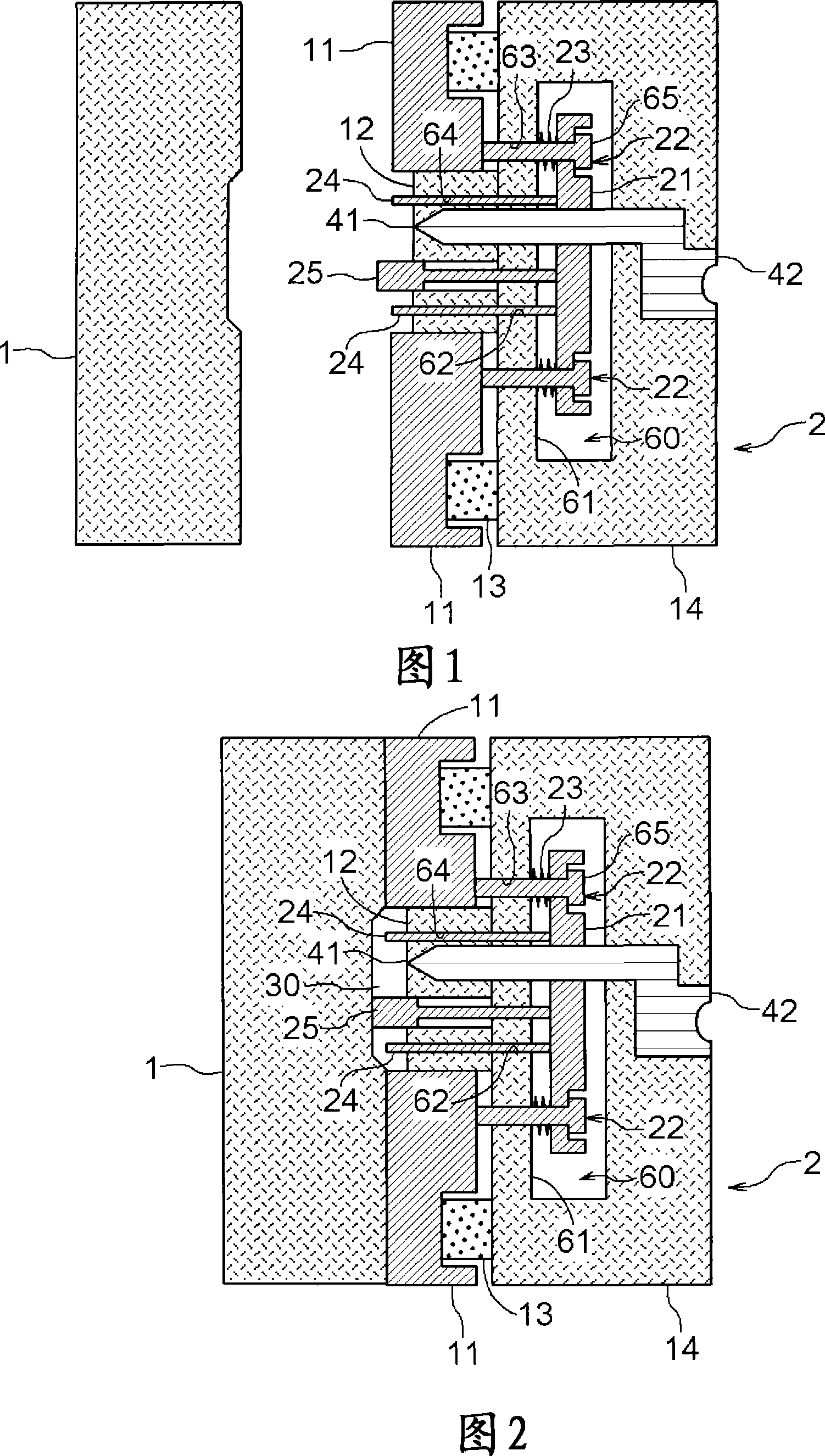
[0053] First, a mold for injection compression molding according to a first embodiment will be described based on the drawings.
[0054] Fig. 1 is a schematic cross-sectional view showing a state in which a mold is opened.
[0055] In this figure, the first mold 1 is formed in a square shape as in the conventional one, and the surface facing the second mold 2 is engraved with a shape for forming the surface of an injection compression molded product.
[0056] On the other hand, the second mold 2 is formed in a square shape with a width and a height corresponding to those of the first mold 1 . In addition, the surface of the second mold 2 opposite to the first mold 1 is equipped with a compression block 12 engraved with a shape for forming the back surface of the injection compression molded product. Around the compression block 12, an outer peripheral plate 11 is provided for constituting the outer peripheral shape of the injection compression molded product. Like the second...
no. 2 Embodiment approach
[0083] In this second embodiment, the mold for injection compression molding according to the present invention is used as a mold for simultaneous injection compression molding and decoration. Next, an injection compression molding simultaneous decoration mold according to a second embodiment will be described based on the drawings. The description of the same configuration as that of the above-mentioned first embodiment is omitted.
[0084] Fig. 8 is a schematic cross-sectional view showing a state in which the mold is opened.
[0085] In this figure, the decorative sheet 3 is arranged between the first mold 1 and the second mold 2 arranged to face each other. The decorative sheet 3 is formed of a base sheet 51, a decorative layer 50, and the like. The decorative layer 50 is composed of a pattern layer 52 and an adhesive layer 53 (see FIG. 15 ), and is used when only the decorative layer 50 is to be transferred onto the molded resin 31 .
[0086] Fig. 9 is a schematic sect...
no. 3 Embodiment approach
[0113] This third embodiment is another embodiment of the above-mentioned second embodiment. Next, a simultaneous decoration mold for injection compression molding according to a second embodiment will be described based on the drawings. The description of the same configuration as that of the above-mentioned second embodiment is omitted.
[0114] Fig. 16 is a schematic cross-sectional view showing a state in which the mold is opened.
[0115] In this figure, the first mold 1 includes a suction device 70 that sucks the decorative sheet 3 arranged between the first mold 1 and the second mold 2 . The suction device 70 includes a communication portion 71 communicating with the mold cavity 1a formed in the first mold 1 for forming a molding space, and a suction device 72 communicating with the communication portion 71 and sucking air. The suction device 70 can hold the decorative sheet 3 in a state along the mold cavity 1 a by suctioning the decorative sheet 3 . Therefore, defo...
PUM
| Property | Measurement | Unit |
|---|---|---|
| Film thickness | aaaaa | aaaaa |
| Thickness | aaaaa | aaaaa |
| Vertical size | aaaaa | aaaaa |
Abstract
Description
Claims
Application Information