
Joint with increased splay angle

A technology of external joints and constant velocity universal joints, applied in the direction of connection, elastic coupling, extracellular fluid disease, etc., can solve problems such as track edge damage

Inactive Publication Date: 2008-07-09
GKN DRIVELINE DEUTSCHLAND GMBH
View PDF0 Cites 11 Cited by
  • Summary
  • Abstract
  • Description
  • Claims
  • Application Information

AI Technical Summary

Problems solved by technology

It is expected that increasing the opening angle will increase the risk of track edge damage at the axial end of the outer ball track at the open end of the outer joint

Method used


Image

  • Joint with increased splay angle
  • Joint with increased splay angle
  • Joint with increased splay angle

Examples


Embodiment Construction

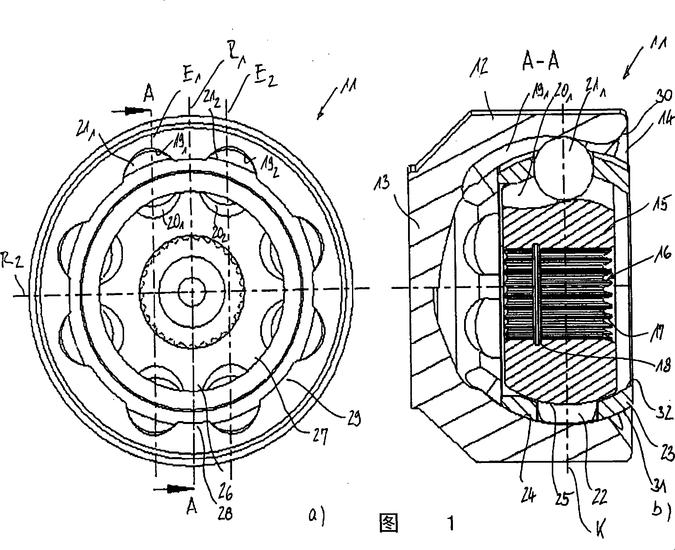
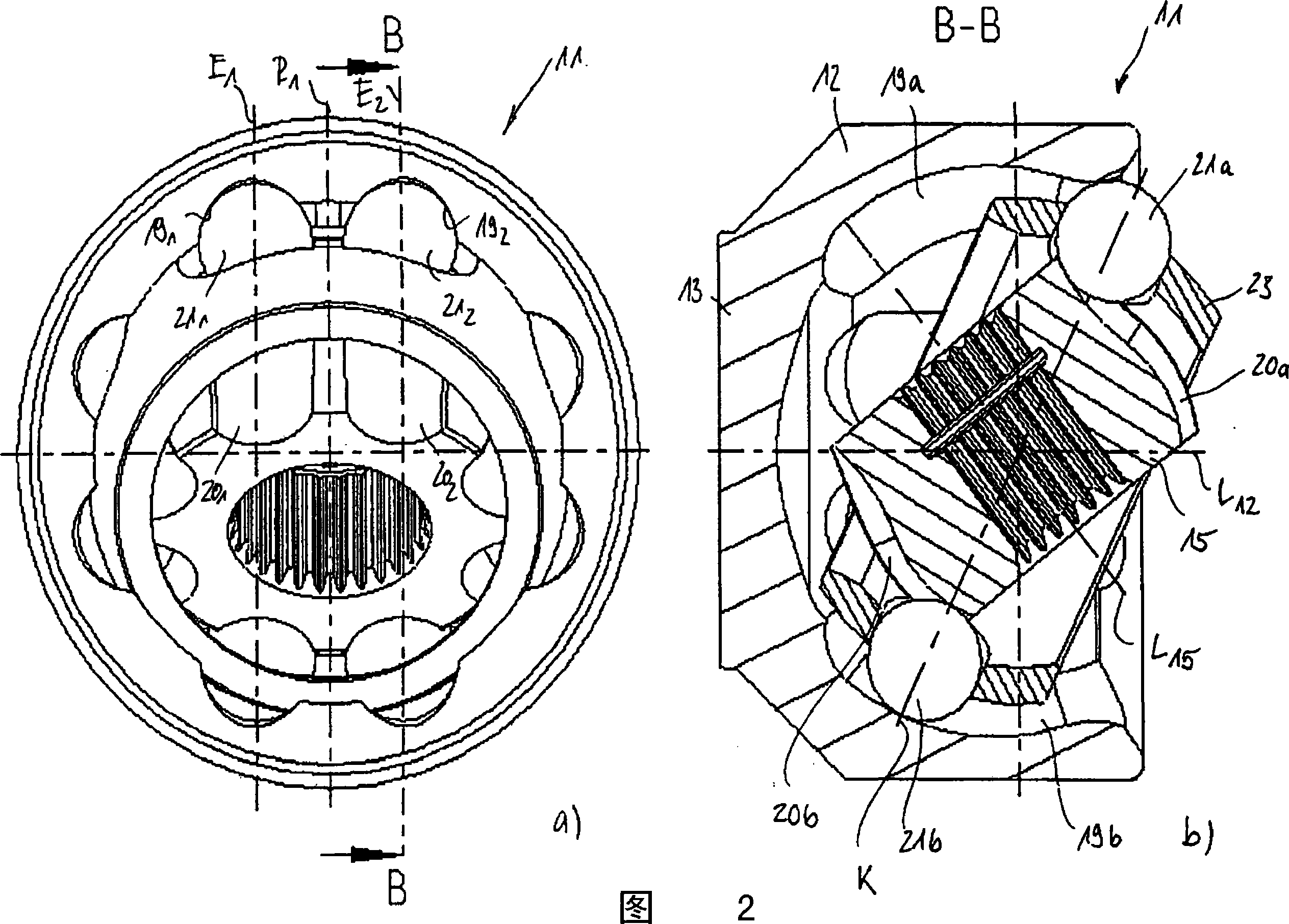
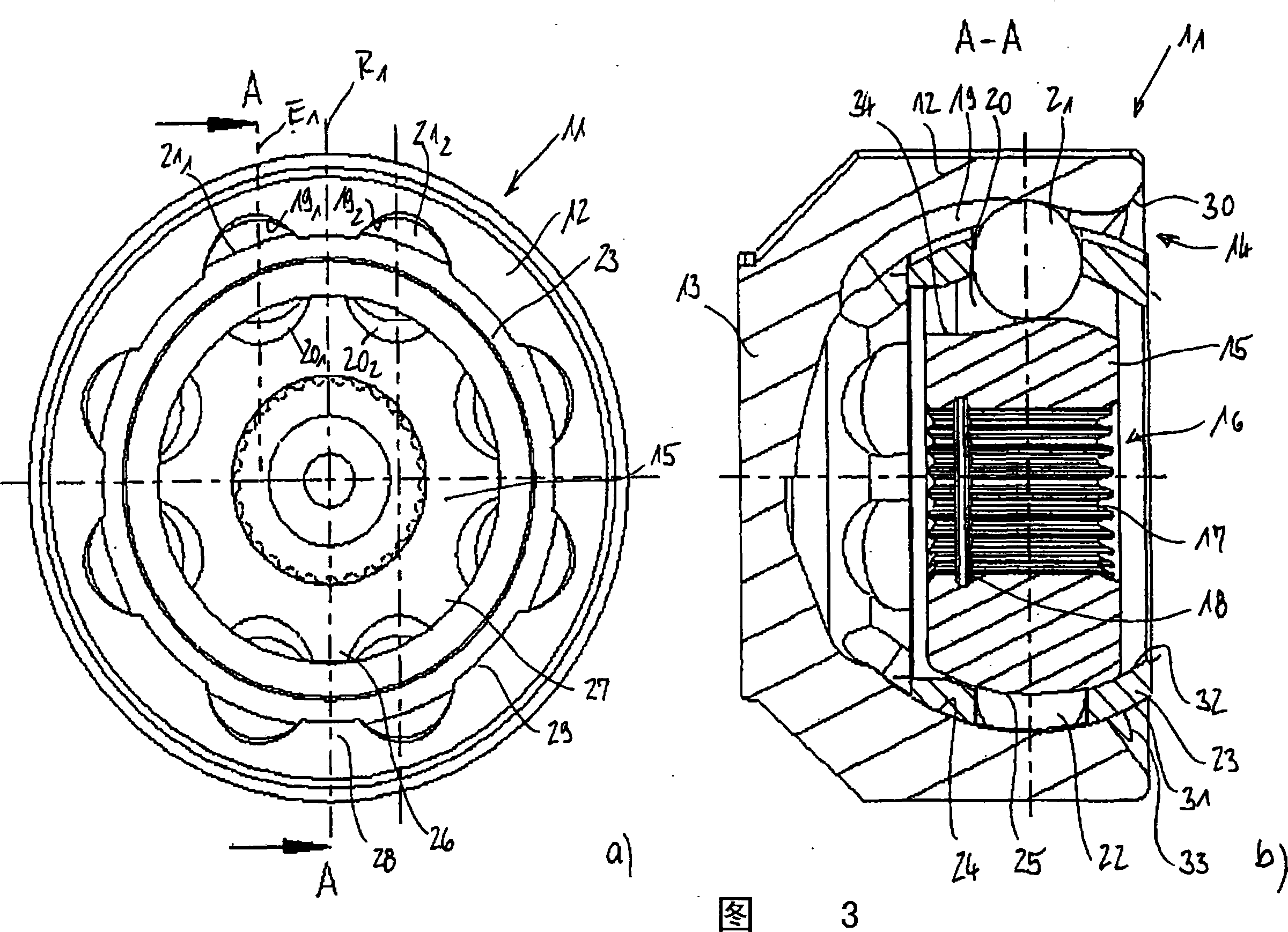
[0028] The two diagrams in FIG. 1 will be jointly described below. The figure shows a so-called double ball joint in which the longitudinal extension of adjacent pairs of rails is defined by parallel planes. Using a total of eight circumferentially distributed balls, two pairs of parallel planes can be determined as the geometrical position of the centerline of the track. Two planes E1 , E2 are marked with dotted lines, which are located symmetrically with respect to the first radial plane R1 . A second radial plane R2 is positioned perpendicularly to the first radial plane R1, the plane of the associated ball track extending parallel thereto is not shown here. The constant velocity universal joint 11 comprises an outer joint member 12 having a bottom 13 formed thereon with an opening 14 of the joint positioned axially opposite the bottom 13 . Located in the outer joint part 12 is an inner joint part 15 which has an insertion opening 16 showing internal teeth 17 for introduc...


PUM


Abstract

The invention relates to a constant-velocity joint (11) with a joint outer piece (12) with outer ball tracks (19), a joint inner piece (15) with inner ball tracks (20), torque-transmitting balls (21), retained in pairs in adjacent outer and inner ball tracks (19, 20) and a ball cage (23), housing the balls (21) in cage windows (22) and maintaining a common mid-plane, whereby the track lines of the paired outer ball tracks (19) and inner ball tracks (20) are mirror images about the mid-plane of the constant-velocity joint, whereby one type of outer and inner ball tracks (19, 20) have a track shape at at least one axial end section (34) such that a ball (21) entering said axial end section (34) on a bending of the joint is released from torque transmission between the paired inner and outer ball tracks (19, 20).

Description

technical field [0001] The invention relates to a constant velocity universal joint (11), which has an outer joint part with an outer ball track, an inner joint part with an inner ball track, a plurality of torque transmission balls and a ball cage, the torque transmission The balls are held in pairs of outer and inner ball tracks associated with each other, and the ball cage receives the torque transmitting balls in the window of the cage and keeps them in a common central plane K, wherein the outer and inner ball tracks associated with each other The trajectory of the ball track and the trajectory of the inner ball track extend mirror-symmetrically with respect to the center plane K of the constant velocity universal joint. Said mirror-symmetrical manner of track trajectory extension refers to the longitudinal centerline of the ball track, which corresponds to the course of the center of the ball within the ball track. The plane formed by the intersecting longitudinal axes ...

Claims


Application Information

Patent Timeline
IPC IPC(8): F16D3/224F16D3/223F16D3/2233
CPCF16D3/2233Y10T403/32655F16D2003/22309A61P7/02
Inventor H·哈尼谢费格
Owner GKN DRIVELINE DEUTSCHLAND GMBH
Learn More