Antenna amount transmission method

A technology of transmission method and quantity, applied in transmission monitoring, transmission system, diversity/multi-antenna system, etc., can solve the problem that the number of antennas cannot be accurately obtained

Inactive Publication Date: 2008-07-16
ZTE CORP
View PDF1 Cites 9 Cited by
  • Summary
  • Abstract
  • Description
  • Claims
  • Application Information

AI Technical Summary

Problems solved by technology

[0007] The technical problem solved by the present invention is to provide a method for transmitting the numb

Method used


Image

  • Antenna amount transmission method
  • Antenna amount transmission method

Examples


no. 1 example

[0047] It is stipulated that when the physical broadcast channel is one antenna, the data time domain mapping order is {1, 2, 3, 4}; when the physical broadcast channel is two antennas, the data time domain mapping order is {2, 3, 4, 1 }; when the physical broadcast channel is four antennas, the data time-domain mapping sequence is {3, 4, 1, 2}.

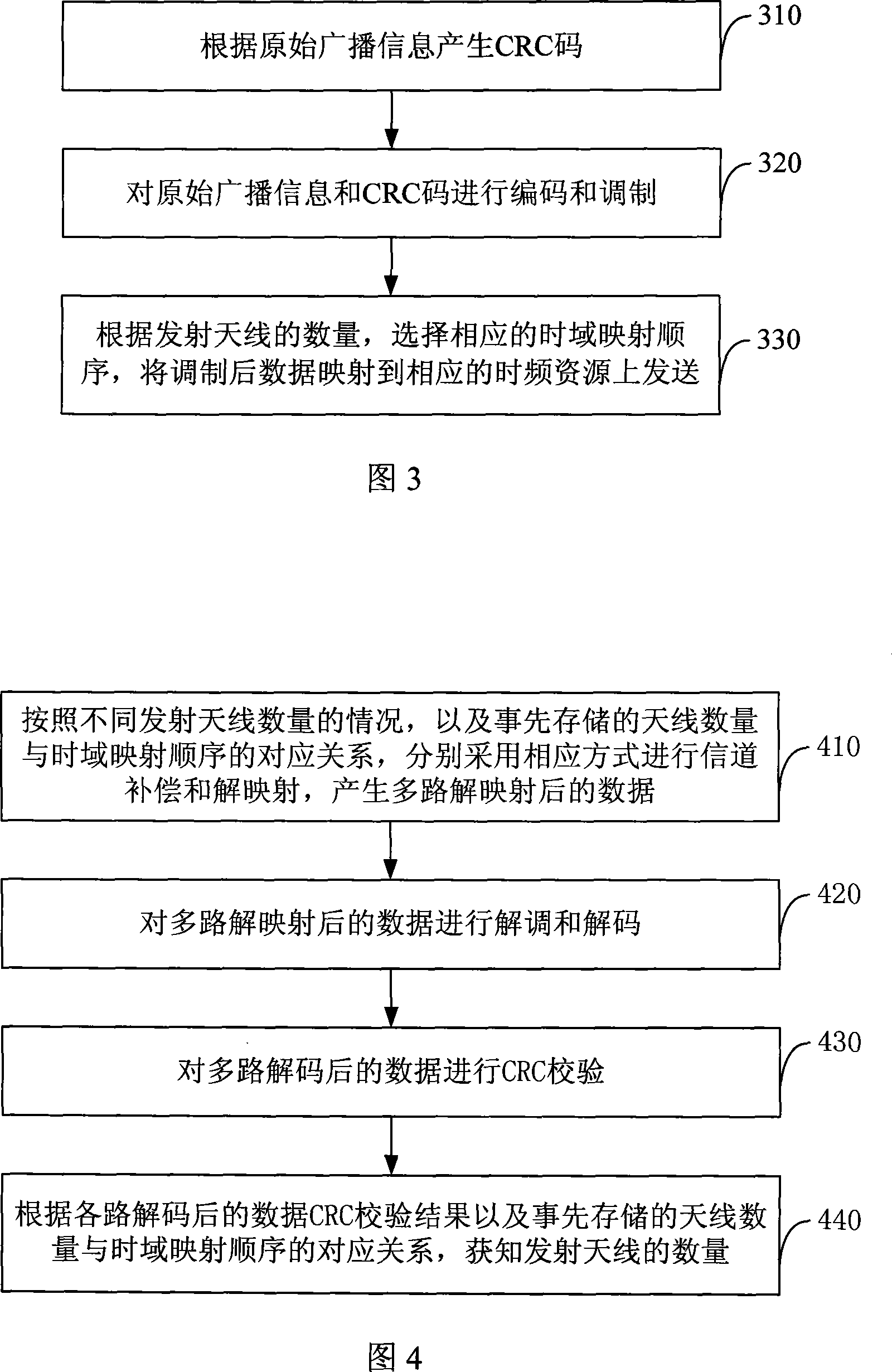
[0048] At the sending end, firstly, CRC bits are generated according to the original information bits; then, the original information bits and CRC bits are encoded and modulated; then, according to the number of transmitting antennas, {2, 3, 4, 1} time-domain mapping is selected In sequence, the modulated data is mapped to corresponding time-frequency resources and sent out.

[0049]At the receiving end, firstly, channel compensation and demapping are performed in a corresponding manner according to the number of different transmitting antennas in turn to generate multi-channel de-mapped data, and then, the multi-channel de-mapped dat...

no. 2 example

[0051] It is stipulated that when the physical broadcast channel is one antenna and two antennas, the time-domain mapping order of data is {1, 2, 3, 4}; when the physical broadcast channel is four-antenna, the data time-domain mapping order is {2, 3 , 4, 1}.

[0052] At the sending end, first, generate CRC bits according to the original information bits; then, encode and modulate the original information bits and CRC bits; then, select {1, 2, 3, 4} time-domain mapping according to the number of transmitting antennas In sequence, the modulated data is mapped to corresponding time-frequency resources and sent out.

[0053] At the receiving end, firstly, channel compensation and demapping are performed in a corresponding manner according to the number of different transmitting antennas in turn to generate multi-channel de-mapped data, and then, the multi-channel de-mapped data is demodulated and decoded, and then, The CRC check is performed on the decoded data of multiple channe...

no. 3 example

[0055] It is stipulated that when the physical broadcast channel is one antenna and two antennas, the time-domain mapping order of data is {1, 2, 3, 4}; when the physical broadcast channel is four-antenna, the data time-domain mapping order is {4, 3 , 2, 1}.

[0056] At the sending end, first, generate CRC bits according to the original information bits; then, encode and modulate the original information bits and CRC bits; then, select {1, 2, 3, 4} time-domain mapping according to the number of transmitting antennas In sequence, the modulated data is mapped to corresponding time-frequency resources and sent out.

[0057] At the receiving end, firstly, channel compensation and demapping are performed in a corresponding manner according to the number of different transmitting antennas in turn to generate multi-channel de-mapped data, and then, the multi-channel de-mapped data is demodulated and decoded, and then, The CRC check is performed on the decoded data of multiple channe...


PUM


Abstract

The invention discloses a transmission method for antenna quantity which aims to solve the problem that the antenna quantity fails to be accurately obtained in the prior art. The method comprises that: a corresponding relation is established between the quantity of transmitting antennas and time-domain mapping sequences of the data on a physical channel, and is respectively saved on the sending end and the receiving end; the sending end adopts a corresponding time-domain mapping sequence to send data on the physical channel according to the quantity of the antennas; after the receiving end receives the data, a demapping, a decoding and a CRC check are made according to different quantities of the transmitting antennas and the corresponding relation between the quantity of the antennas and the time-domain mapping sequences which is stored in advance, the quantity of the transmitting antennas is confirmed according to the result of the CRC check. The method of the invention can well detect the quantity of the antennas, particularly can well distinguish two antennas and four antennas, thereby assuring the decoding performance of the data; and the method is simple and is easy to realize.

Description

technical field [0001] The invention relates to the field of mobile communication, in particular to a method for transmitting the number of antennas. Background technique [0002] As shown in FIG. 1 , it is a schematic diagram of an LTE (Long Term Evolution) system frame structure. In the LTE system, a 10ms radio frame is divided into two half frames, each half frame is divided into 10 time slots with a length of 0.5ms, and two time slots form a subframe with a length of 1ms, and a half frame contains 5 subframes. frame. [0003] As shown in FIG. 2 , it is a schematic diagram of sending a physical broadcast channel in an LTE system. The sending period of the physical broadcast channel is 40ms, wherein the physical broadcast channel is sent every 10ms, and within a period, the physical broadcast channel sends the same information each time. In order to achieve accurate timing in a cycle, the LTE standard stipulates that by using different scrambling codes to distinguish th...

Claims


Application Information

Patent Timeline
IPC IPC(8): H04L1/02H04B7/04H04B17/00
Inventor 夏树强戴博梁春丽郝鹏
Owner ZTE CORP
Why Eureka
Try Eureka