State monitoring method and system

A state monitoring and system-level technology, applied in the field of communication, can solve problems such as the inability to effectively monitor the state of a digital subscriber line access multiplexer, and achieve the effect of facilitating timely positioning

Inactive Publication Date: 2008-07-16
ZTE CORP
View PDF0 Cites 12 Cited by
  • Summary
  • Abstract
  • Description
  • Claims
  • Application Information

AI Technical Summary

Problems solved by technology

[0007] The present invention is made in consideration of the above-mentioned problems. For this reason, the main purpose of the present invention is to provide a s

Method used


Image

  • State monitoring method and system
  • State monitoring method and system

Examples


Embodiment 1

[0028] In this embodiment, a state monitoring method is provided for a digital subscriber line access multiplexer.

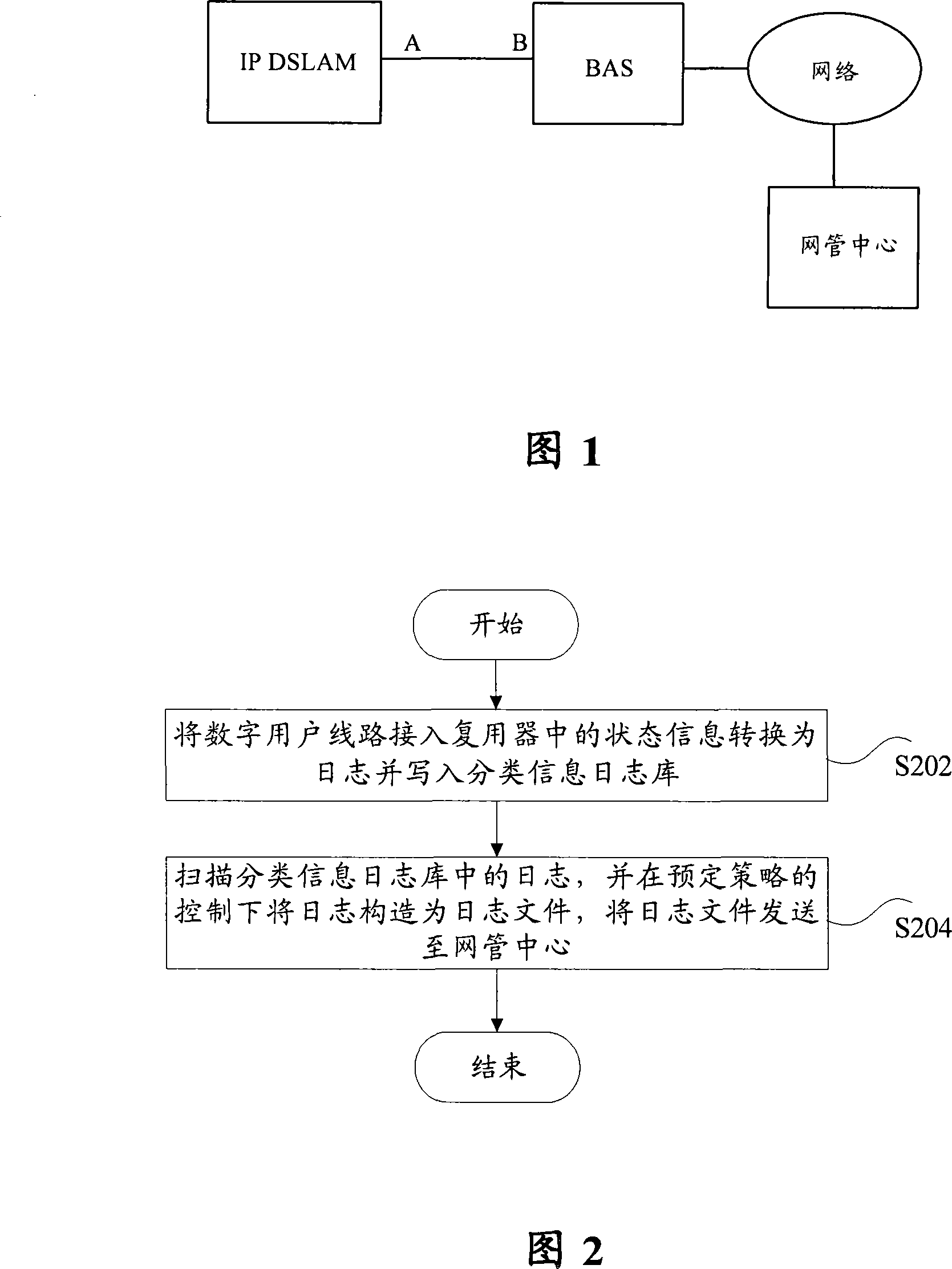
[0029] As shown in Figure 2, the state monitoring method according to this embodiment includes: step S202, converting the state information in the digital subscriber line access multiplexer into a log and writing it into the classification information log library; and step S204, scanning the classification information log in the log library, and construct the log into a log file under the control of a predetermined policy, and send the log file to the network management center.

[0030] Wherein, the status information may include: thread status information and system-level status parameters.

[0031] In addition, the thread state information is obtained by the working thread; the system-level state parameters are obtained by the preset collection module.

[0032] The following will be described in conjunction with specific examples.

example 1

[0033] Example 1: Use the log to forward the status information of each thread of the system to the network management center

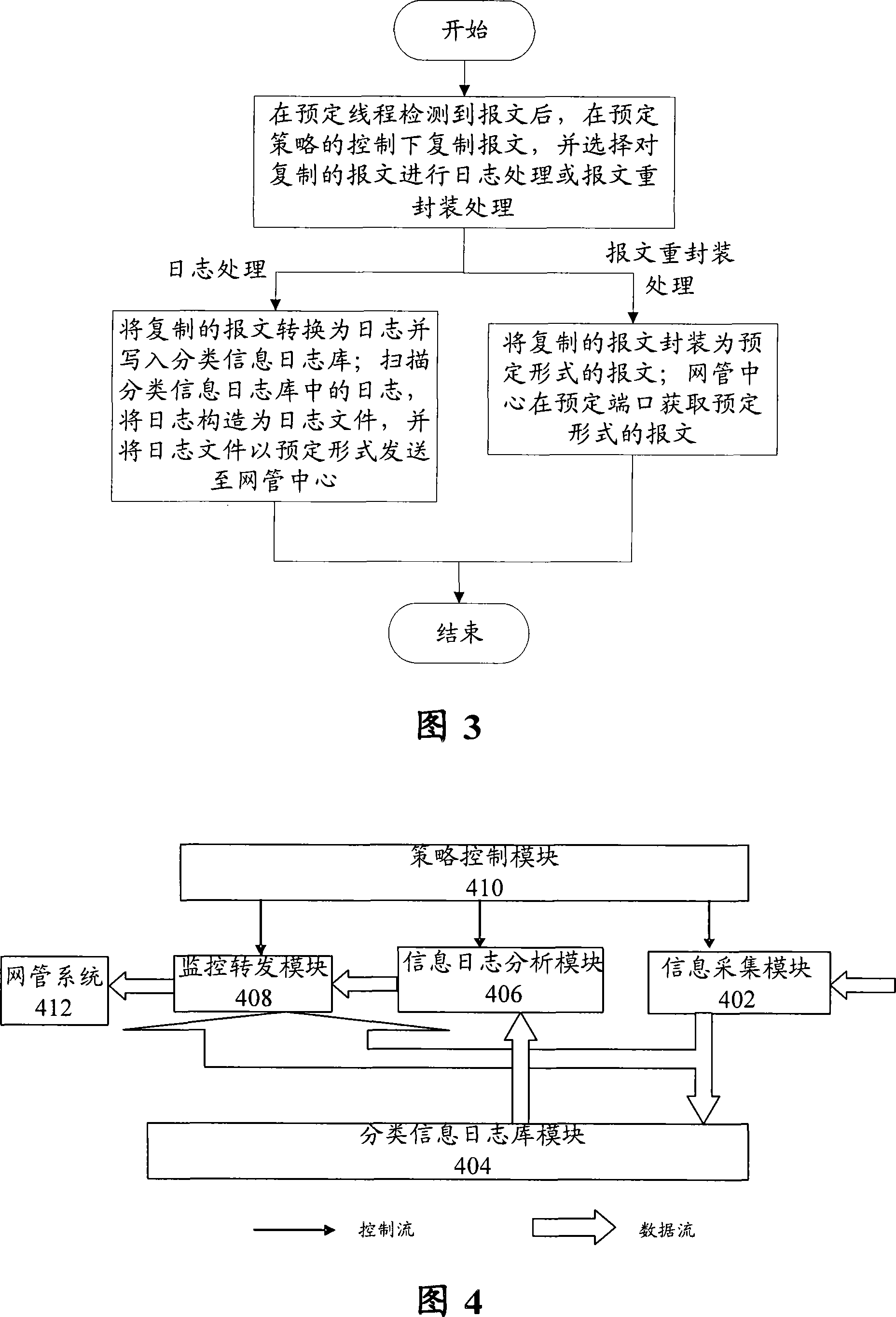
[0034] (1) Each working thread in the system writes its own status information into the thread log library through the information collection module in real time;

[0035] (2) The information log analysis module regularly scans the log of the thread log library, scans no more than the set number of records until the end, updates and saves the next scanning start;

[0036] (3) The policy control module determines whether to notify the monitoring and forwarding module to construct a log file according to the set strategy, and send it to the network management center in the form of the file transfer protocol (FTP);

[0037] (4) The network management center obtains the thread log and analyzes it, and this process is completed.

example 2

[0038] Example 2: Use logs to forward system-level status information to the network management center

[0039] (1) The acquisition module actively and regularly acquires system-level status parameters and writes them into the system status log library;

[0040] (2) The information log analysis module regularly scans the log of the system state log library, scans no more than the set number of records until the end, updates and saves the next scanning start;

[0041] (3) The strategy control module decides whether to notify the monitoring and forwarding module to construct a log file according to the strategy set, and send it to the network management center in the form of FTP;

[0042] (4) The network management center obtains the system status log and analyzes it, and this process is completed.


PUM


Abstract

The invention discloses a state monitoring method which comprises that: the step S202: state information in a digital user line accessed to a multiplexer is converted to logs and written to a category message log library; the step S204: the logs in the category message log library are scanned and constructed to a log file under the control of a predetermined strategy; the log file is sent to a network management center. In addition, the invention also provides a state monitoring system. Through using the invention, the invention can make the best of a log system included in a general network element, monitors an inner state of IP DSLAM equipment under the condition of increasing no extra cost and can examine the state of each working thread inside the DSLAM equipment in long-distance; in addition, the invention can also examine a management channel, abnormal service messages, etc. in long-distance and is convenient to position the management channel and the problems existing in a user side service channel in time.

Description

technical field [0001] The present invention relates to the field of communications, and in particular, to a state monitoring method and system for a digital subscriber line access multiplexer. Background technique [0002] At present, the management of IP Digital Subscriber Line Access Multiplexer (DSLAM) equipment (network elements) is mainly in the charge of the network management center. A network management center needs to manage multiple network element equipment at the same time. Although it has relatively complete management functions, It is impossible to do a finer state analysis of each network element. Especially when there is an abnormality in the service or management channel of the network element, the conventional network management function cannot effectively locate and analyze it. Moreover, the current network management logs basically focus on operational records, which cannot effectively monitor the internal status of network elements, and cannot provide ...

Claims


Application Information

Patent Timeline
IPC IPC(8): H04L12/26H04L12/24
Inventor 陈祥荣
Owner ZTE CORP
Why Eureka
Try Eureka