Polishing machine

A polishing machine and polishing chamber technology, applied in the field of polishing machines, can solve the problems of high consumption, reduced air flow, high pressure loss, etc.

Inactive Publication Date: 2010-05-12
WUXI BUHLER MASCH MFG CO LTD
View PDF11 Cites 0 Cited by
  • Summary
  • Abstract
  • Description
  • Claims
  • Application Information

AI Technical Summary

Problems solved by technology

The disadvantage here is that the screen baskets usually have ribs transverse to the air flow or the spacing of the air guide housing is in some cases too great and the flow velocity of the passing air is lower in these regions.
[0005] The production of hollow shafts with multiple openings is complex and due to the small opening cross-sections high pressure losses can occur, which leads to reduced air flow and / or increased fan performance

Method used


Image

  • Polishing machine
  • Polishing machine
  • Polishing machine

Examples


Embodiment Construction

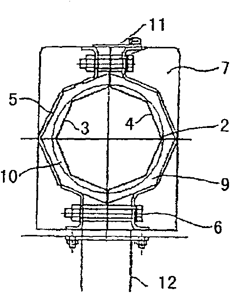
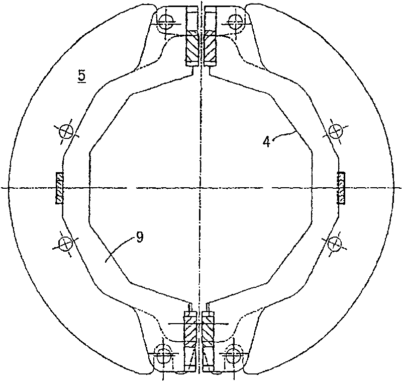
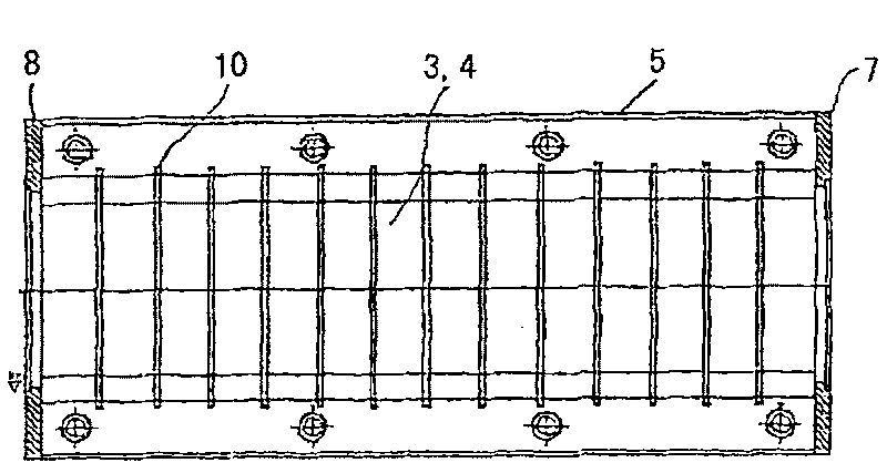
[0025] A polishing machine shown here only in the part to be considered has an annular rotor 1, which is equipped with usual polishing tools 18, such as bumps. In the region of the polishing tools, the rotor 1 consists of an octagonal The sieve 2 is surrounded by two sieve plates 3 and 4. The sieve 2 is surrounded by a two-piece sieve basket 5 in the form of a plate sleeve, which is formed by two half shells. The sieve plate 3 , 4 and the screen basket 5 are connected by means of screw connections 6 and spacer sleeves to a self-supporting unit which is closed on the end sides with end plates 7, 8. There is a uniform narrow gap between the screen 2 and the screen basket 9. This achieves a uniform and high air velocity which only allows a slight tendency to deposit the ground powder.

[0026] The half-shells of the screen basket 5 have inwardly protruding ribs 10 of low height, which are advantageously provided with plug noses. The half shells of the screen basket 5 preferably ...


PUM


Abstract

The invention relates to a polishing machine for rice or other cereals, said machine comprising an octagonal strainer basket (5) and a polishing compartment. The strainer basket (5) comprises two curved walls in the form of shells comprising inwardly projecting ribs (10). The two halves are connected to a divided strainer (2), preferably by means of screwing and spacers, in order to form a supporting strainer basket (5).

Description

technical field [0001] The invention relates to a polishing machine, especially a polishing machine or a grinding machine for polishing or grinding rice or wheat. Background technique [0002] Polishing or grinding machines with horizontally or vertically arranged grinding or polishing rotors for rice or other cereals are known from the prior art. For example EP-A-699478 or EP-A-646414 disclose machines with a vertically arranged rotor on which grinding or polishing tools are provided. The rotor and the tool are surrounded at a distance by a screen, which in turn is accommodated in a screen basket. The basket is surrounded by a housing so that ground or polished products cannot escape uncontrollably. The housing can be a solid housing or have an opening for a viewing window. Furthermore, the rotor can be designed as a hollow shaft and have openings in the region of the tool for feeding air and / or humidified air and / or water into the treatment chamber. Likewise, the air s...

Claims


Application Information

Patent Timeline
Patent Type & Authority Patents(China)
IPC IPC(8): B02B3/04
CPCB02B3/04
Inventor F-O·格利茨M·布罗克费尔德
Owner WUXI BUHLER MASCH MFG CO LTD
Why Eureka
Try Eureka