Novel melt-blowing production equipment

A production equipment and melt-blown technology, applied in spinneret assembly, filament forming process, filament/line forming, etc., can solve the problems of narrow nozzle width, low work efficiency, long residence time, etc., to achieve fluid pressure Reduce, improve work efficiency, the effect of uniform exit speed

Inactive Publication Date: 2022-03-04
WENZHOU POLYTECHNIC
View PDF0 Cites 0 Cited by
  • Summary
  • Abstract
  • Description
  • Claims
  • Application Information

AI Technical Summary

Problems solved by technology

[0004] The purpose of the present invention is to solve the problem that the width of the nozzle in the melt blown equipment in the prior art is narrow, which leads to large energy consumption, low work efficiency, and the uneven speed of the polymer melt at the outlet of the die. For a long time, the polymer will be thermally degraded, resulting in low product quality, which will affect product sales. A new type of melt blown production equipment is proposed

Method used


Image

  • Novel melt-blowing production equipment
  • Novel melt-blowing production equipment
  • Novel melt-blowing production equipment

Examples


Embodiment 1

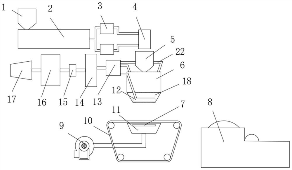
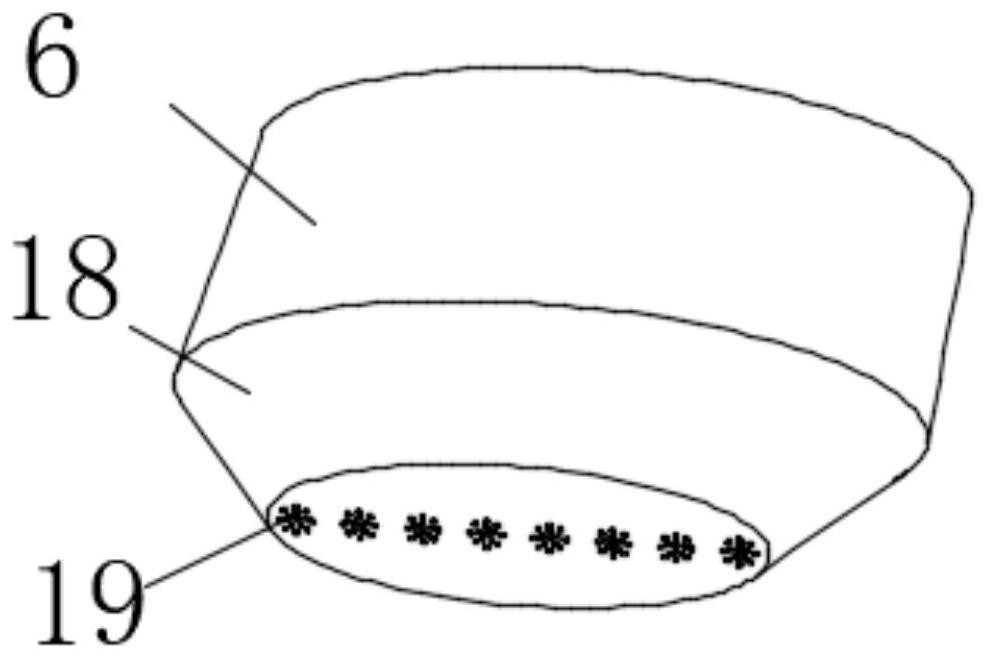
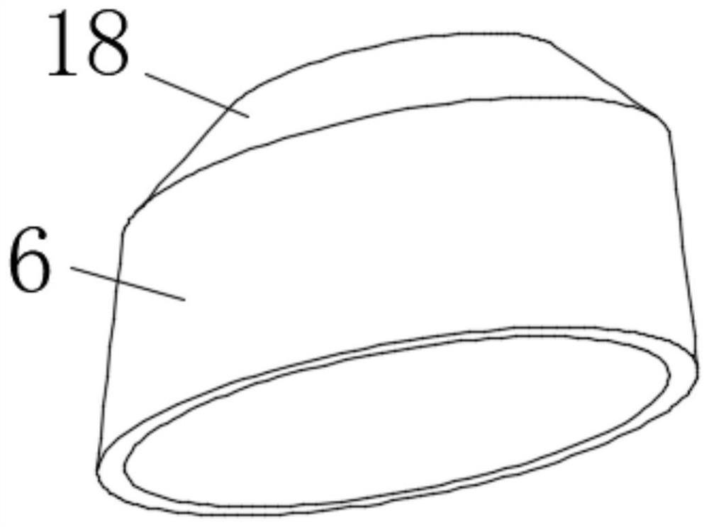
[0028] refer to Figure 1-4 , a new type of melt-blown production equipment, including a screw feeder 2, an elliptical manifold 6, a mesh belt receiver 10, an air compressor 17, and a trimming and winding machine 8, and the screw feeder 2 is connected through a plurality of pipelines. With the same gear metering pump 4, the bottom of the elliptical manifold 6 is fixedly connected with the nozzle 18, the gear metering pump 4 is located directly above the elliptical manifold 6, the mesh belt receiver 10 is located directly below the nozzle 18, and the trimming and winding machine 8 Located on one side of the mesh belt receiver 10, the air compressor 17 is connected to an air storage tank 16 through a pipeline, and the air storage tank 16 is connected to a heater 14 through a pipeline, and a device for distributing air The shunt component of the shunt.

Embodiment 2

[0030] refer to Figure 1-4 , a new type of melt-blown production equipment, including a screw feeder 2, an elliptical manifold 6, a mesh belt receiver 10, an air compressor 17, and a trimming and winding machine 8, and the screw feeder 2 is connected through a plurality of pipelines. With the same gear metering pump 4, the bottom of the elliptical manifold 6 is fixedly connected with the nozzle 18, the gear metering pump 4 is located directly above the elliptical manifold 6, the mesh belt receiver 10 is located directly below the nozzle 18, and the trimming and winding machine 8 Located on one side of the mesh belt receiver 10, the air compressor 17 is connected to an air storage tank 16 through a pipeline, and the air storage tank 16 is connected to a heater 14 through a pipeline, and a device for distributing air A splitter assembly for splitting the flow, the splitter assembly includes a flow divider 13 fixedly communicated with the heater 14 through a pipeline, and the fl...


PUM


Abstract

The invention belongs to the field of melt-blowing production equipment, particularly relates to novel melt-blowing production equipment, and provides the following scheme aiming at the problems that a nozzle in existing melt-blowing equipment is narrow in breadth, polymer melt is non-uniform in speed and long in residence time at an outlet of a die head, and polymer can be thermally degraded, so that the product quality is not high. The device comprises a spiral feeding machine, an elliptical manifold, a mesh belt receiver, an air compressor and a trimming winding machine, the spiral feeding machine is connected with the same gear metering pump through a plurality of pipelines, and the bottom of the elliptical manifold is fixedly communicated with a spray head. The included angle between the air duct and the axis of the jet hole and the width of the jet hole are reduced, so that the airflow speed in the vertical direction is increased, the airflow temperature is increased, the speed of a polymer solution at a die head outlet is more uniform, the residence time is shortened, and the product quality is improved.

Description

technical field [0001] The invention relates to the technical field of melt blown production equipment, in particular to a novel melt blown production equipment. Background technique [0002] The melt-blowing method uses high-speed hot air flow to rapidly and high-magnify the high-power stretching and solidifying spinning method of the newly extruded polymer melt. The advantage is that the process flow is short, and it can be directly made into non-woven fabrics by spinning. [0003] The width of the nozzle in the existing meltblown equipment is narrow, which leads to high energy consumption and low work efficiency, and the speed of the polymer melt at the outlet of the die is not uniform, the residence time is long, and the polymer will be thermally degraded. Due to the situation, the quality of the product is not high, which affects the sales of the product, so we propose a new type of melt-blown production equipment to solve the above-mentioned problems. Contents of th...

Claims


Application Information

Patent Timeline
Patent Type & Authority Applications(China)
IPC IPC(8): D01D5/253D01D1/10D01D4/02D01D5/084
CPCD01D5/253D01D1/106D01D4/025D01D5/084
Inventor 林潘忠高斌
Owner WENZHOU POLYTECHNIC
Why Eureka
Try Eureka