Shipping tray for optical elements, and optical element shipped therein

A technology for optical components, transport pallets, applied in the field of optical components

Inactive Publication Date: 2008-07-23
NIHON DEMPA KOGYO CO LTD
View PDF0 Cites 4 Cited by
  • Summary
  • Abstract
  • Description
  • Claims
  • Application Information

AI Technical Summary

Problems solved by technology

These problems can cause the optical characteristics of the optical elements 7 to deteriorate, making them unusable
In addition, any toppling of the optical element

Method used


Image

  • Shipping tray for optical elements, and optical element shipped therein
  • Shipping tray for optical elements, and optical element shipped therein
  • Shipping tray for optical elements, and optical element shipped therein

Examples


Embodiment Construction

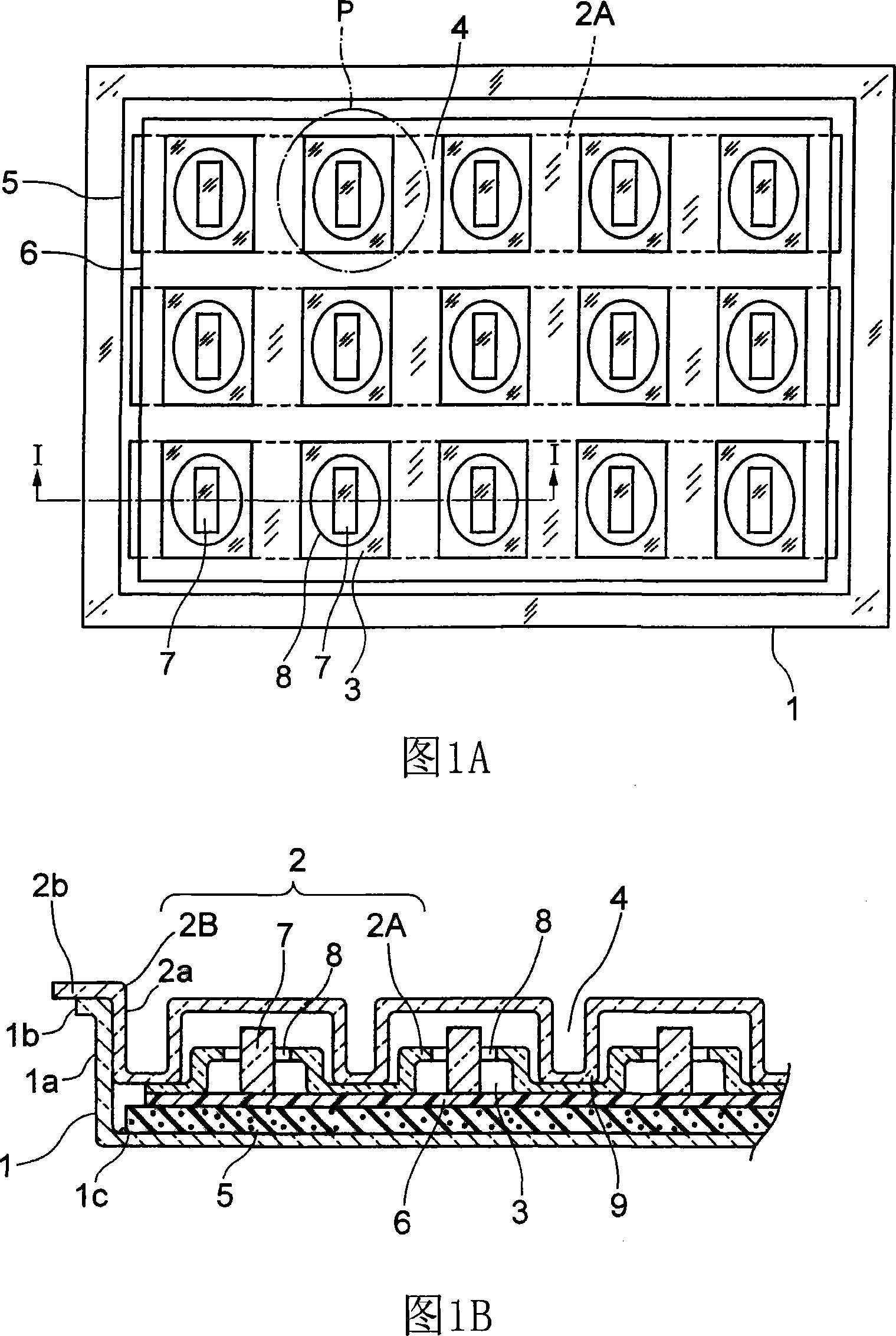
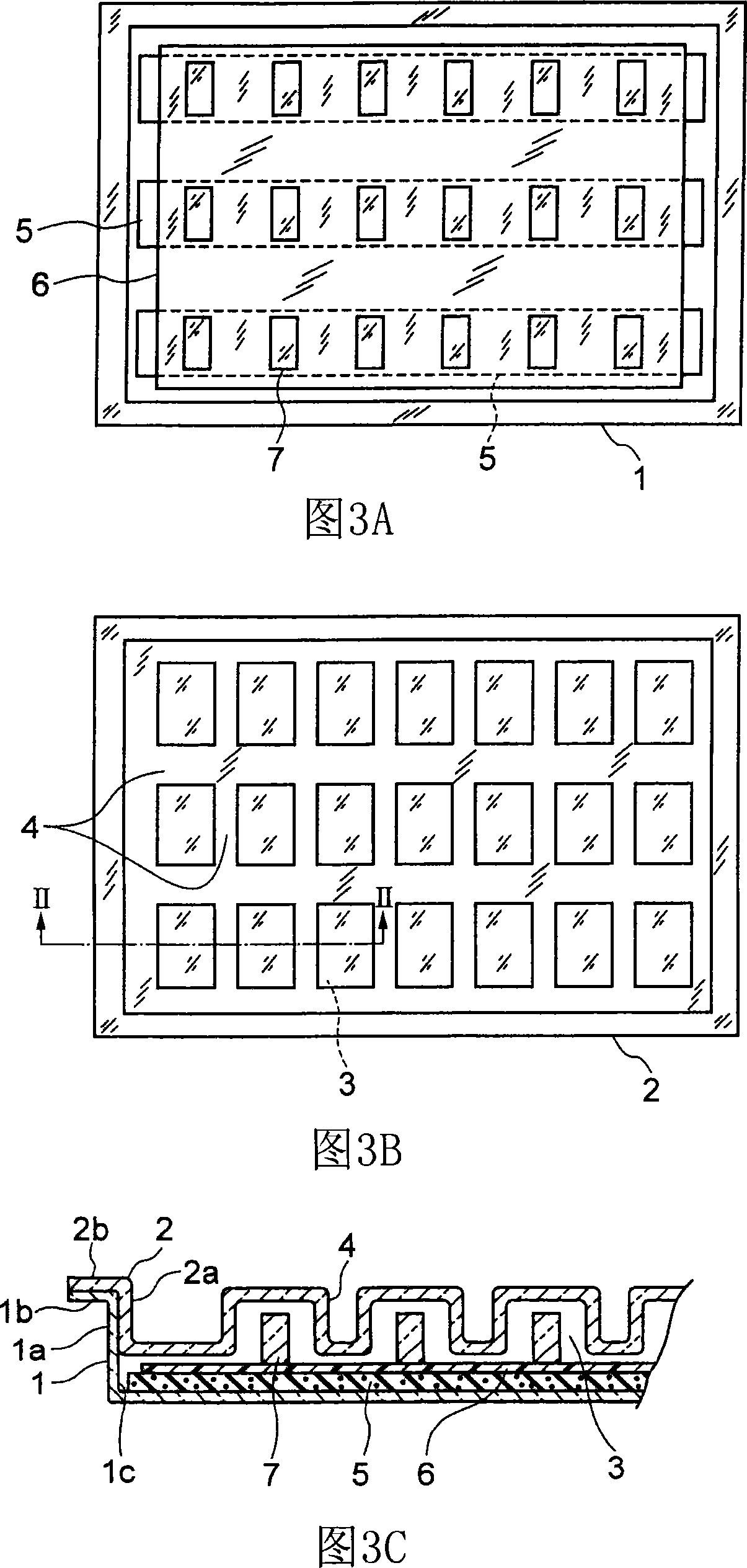
[0025] Fig. 1 shows an embodiment of the transport tray for optical elements according to the present invention, in which Fig. 1A is a plan view with the outer cover removed, and Fig. 1B is a partially enlarged cross-sectional view seen from the direction of arrow II in Fig. 1A . Please note that the same parts as those of the prior art are given the same reference numerals, and their description is simplified or omitted.

[0026] The transport tray for optical elements of the present invention is formed of a main container 1 and a cover 2, each of which is molded from a transparent plastic plate by using a mold (vacuum formation), as described previously. In this case, the cover 2 is composed of an inner cover 2A and an outer cover 2B.

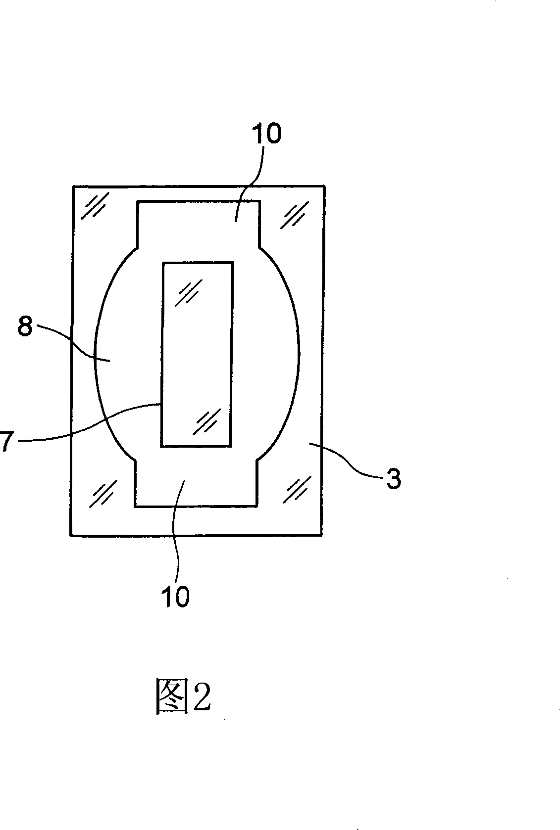
[0027] The inner cover 2A has a plurality of recesses 3 in a rectangular shape formed in the lateral and longitudinal directions by, for example, pressing, in which an oval (e.g., elliptical) hole portion 8 punched by a die is formed in the botto...


PUM


Abstract

The object of the present invention is to provide a shipping tray for optical components, which prevents the tipping of the optical components during transportation and maintains the optimization of the optical properties of the optical components. In a shipping tray for optical components, a single edge of a plurality of optical components each having two main surfaces formed as horizontal flat surfaces, arranged vertically in sequence in the transverse and longitudinal directions on an adhesive tape positioned on the bottom surface of the main container ; A plurality of optical elements are covered by a cover, and a plurality of recesses are formed in the cover for respectively accommodating a plurality of optical elements. Each depression in the cover has a hole portion provided in its stepped portion, into which one of the optical elements is vertically inserted and from which the free edge side protrudes, and the shape of the hole portion is oval.

Description

Technical field [0001] The present invention relates to a transport tray for optical elements (in which optical elements are loaded) and optical elements loaded therein, and more particularly to a transport tray for optical elements that ensures that the characteristics of the optical elements are maintained during transportation. Background technique Background of the invention [0002] Optical elements are made of materials such as crystal or glass, and are used after being assembled into various optical devices such as cameras. Therefore, the demand has recently increased. Such optical elements are usually accommodated, loaded, and transported in transport trays for optical elements formed of plastic (resin). [0003] current technology [0004] Fig. 3 shows a prior art transport tray for optical components, in which Fig. 3A is a plan view with the cover 2 removed, Fig. 3B is a plan view of the cover, and Fig. 3C is from the direction of arrow II-II in Fig. 3B See the partial...

Claims


Application Information

Patent Timeline
IPC IPC(8): B65D71/70B65D85/00B65D81/00B65D43/02B65D1/34B65D25/10B65D77/26G02B7/02
Inventor 高田元生古关亮一
Owner NIHON DEMPA KOGYO CO LTD
Why Eureka
Try Eureka