

Lighting equipment
A technology for an illuminating device and a reflective surface, which is applied to lighting devices, components of lighting devices, lighting and heating equipment, etc., to achieve the effect of reducing costs and reducing the process of installing lenses
Inactive Publication Date: 2008-07-23
KOKUYO CO LTD
View PDF0 Cites 3 Cited by
- Summary
- Abstract
- Description
- Claims
- Application Information
AI Technical Summary
Problems solved by technology
[0005] However, when the device described in the above-mentioned patent document properly irradiates the object with the light of the optical fiber, as mentioned above, it is necessary to adjust the relative distances of the plurality of lenses provided at the front end of the irradiation device so as to irradiate the object with an irradiation range suitable for the object. the light
Method used
View moreImage
Smart ImageViewing Examples

Examples
Embodiment
[0072] Examples of the present invention are described below, but the present invention is not limited to the examples.
[0073]
[0074] The irradiation range of the irradiation light generated by the irradiation device of the above-mentioned embodiment was measured.
Login to View More PUM
 Abstract
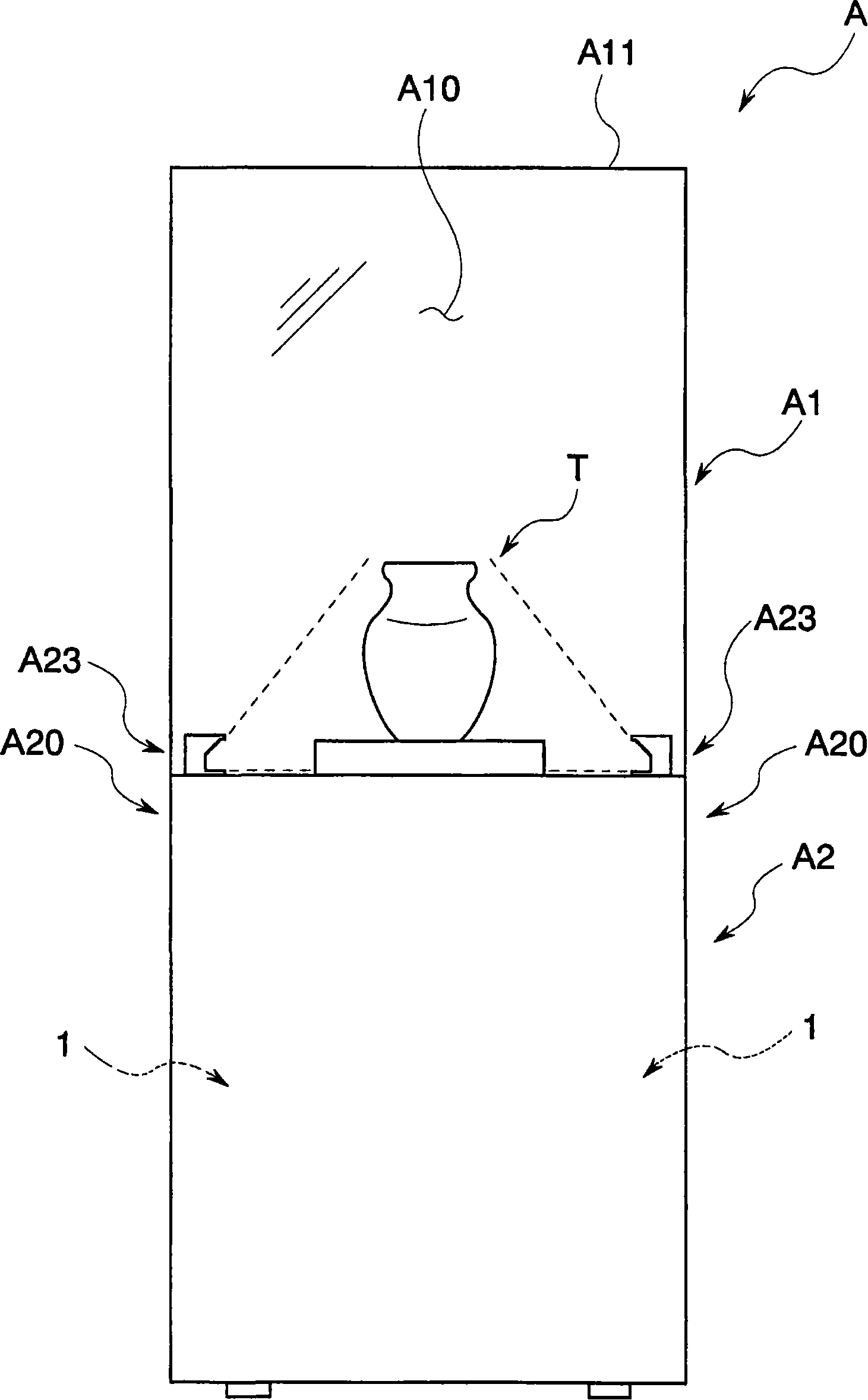
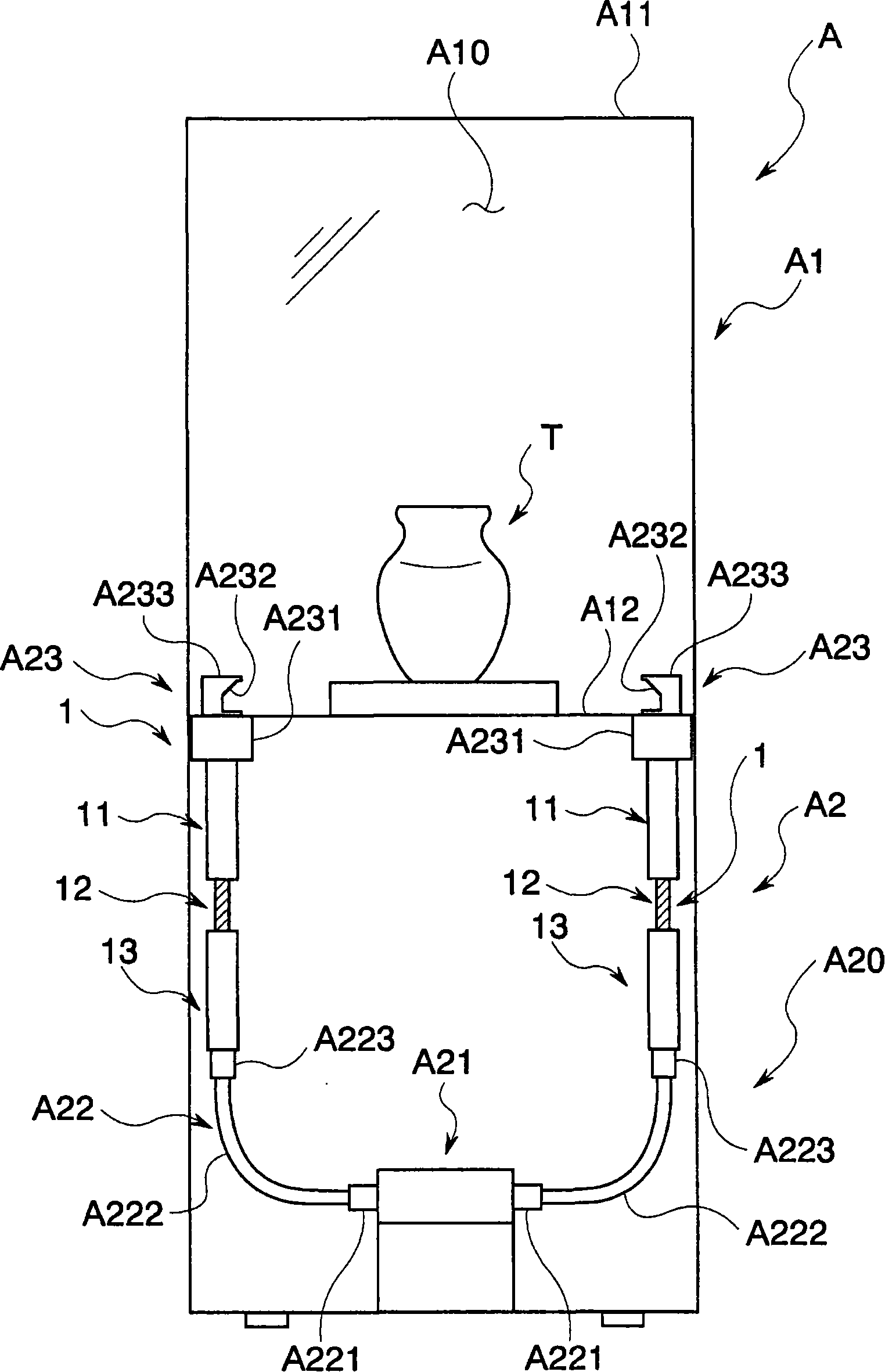
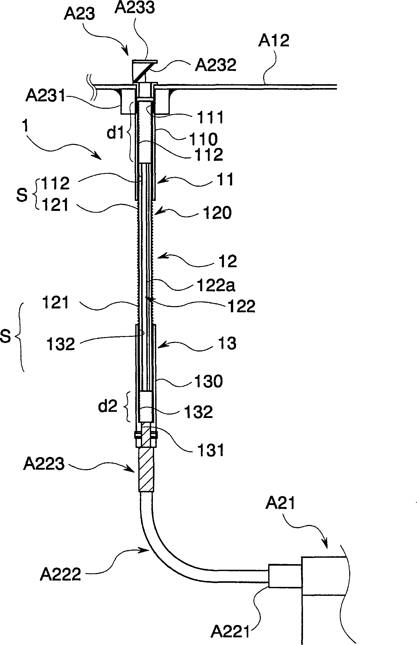
The present invention provides an irradiation device that can effectively avoid the use of a lens and can easily and effectively adjust the irradiation range of light irradiated on an object. It has: an optical fiber part (12) that emits the light incident from the base end from the front end; A side outer cylinder (11); a relative moving part S capable of relatively moving a part of the incidence side outer cylinder (13) and the exit side outer cylinder (11) to a position pushed out from the base end or the front end of the optical fiber part (12).
Description
technical field [0001] The present invention relates to an irradiation device using an optical fiber. Background technique [0002] Conventionally, various irradiation devices using optical fibers have been proposed and widely used as devices capable of appropriately irradiating light in various places (for example, refer to Patent Document 1). [0003] These devices are configured to guide light from a light source to an irradiating tip portion through an optical cable and appropriately emit light from the irradiating tip portion, as listed in the above-mentioned documents. Furthermore, by providing a plurality of lenses at the front end of the irradiation and using a special device for adjusting the relative distance between the lenses, the focus or irradiation range of the irradiation light can be adjusted, and the object can be irradiated appropriately. [0004] Patent Document 1: Special Publication No. 2001-117021 [0005] However, when the device described in the ab...
Claims
Login to View More Application Information
Patent Timeline
 Patent Type & Authority Applications(China)
IPC IPC(8): F21V8/00F21V14/04
CPCG02B6/0008G02B6/0043G02B6/4292G02B23/26
Inventor 山内佳弘
Owner KOKUYO CO LTD