

Method for carrying out butler matrix
A matrix and network technology, applied in the field of Butler matrix beamforming network, which can solve problems such as difficulty and synthesis loss
- Summary
- Abstract
- Description
- Claims
- Application Information
AI Technical Summary
Problems solved by technology
Method used
Image

Examples
Embodiment Construction
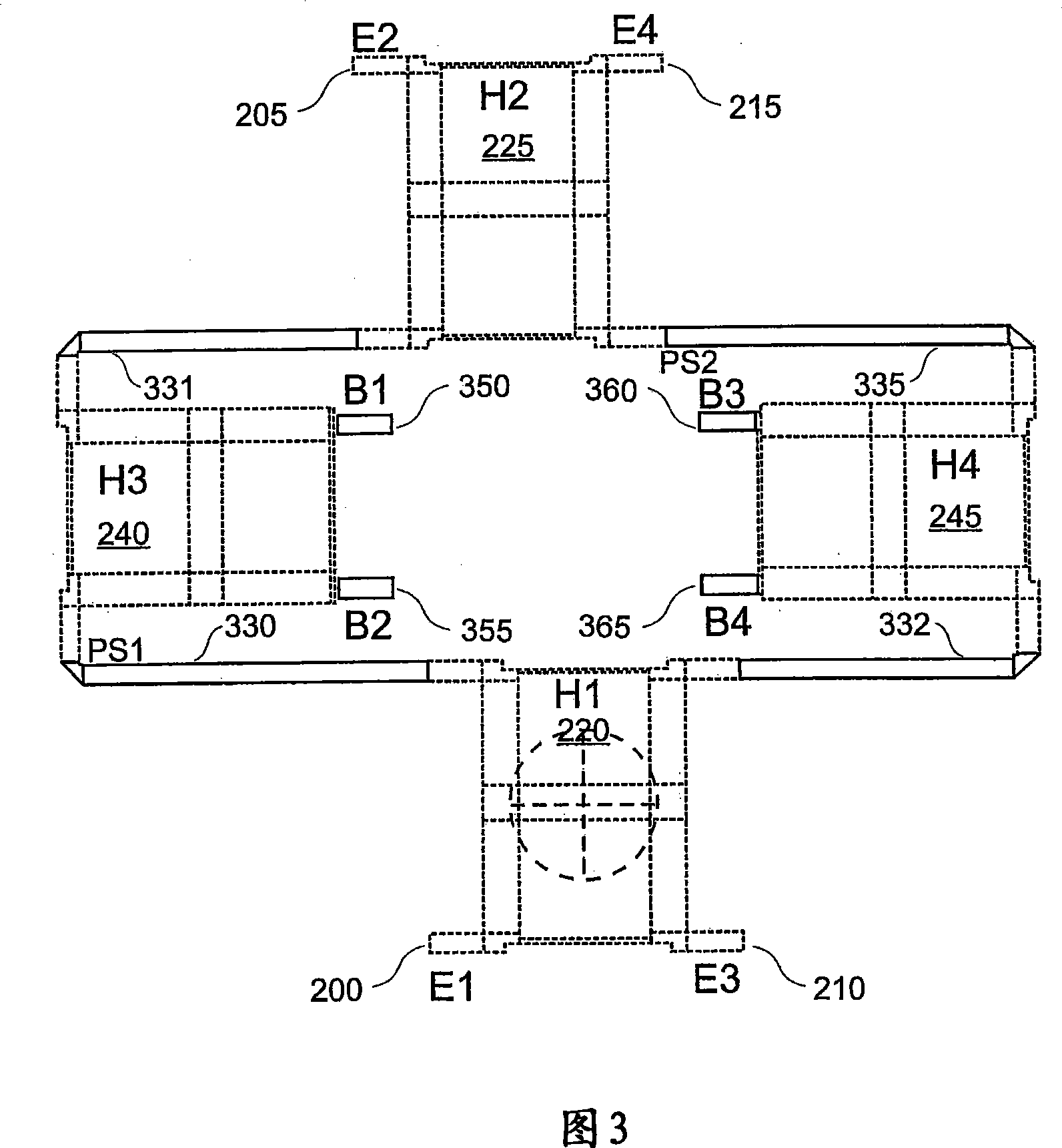
[0047] [45] Reference is now made to Fig. 3, which shows an example embodiment of the novel two-dimensional planar printed circuit board structure of the present invention for a 4×4 Butler matrix with the ability to synthesize beam port pairs.
[0048] [46] The figure includes: four unit ports marked E1 200, E2 205, E3 210 and E4 215, four beam ports marked B1 350, B2 355, B3 360 and B4 365, respectively marked Four mixing units H1 220, H2 225, H3 240 and H4 245, two 45° phase shifters denoted PS1 330 and PS2 335 respectively, and two connectors denoted 331 and 332 respectively.
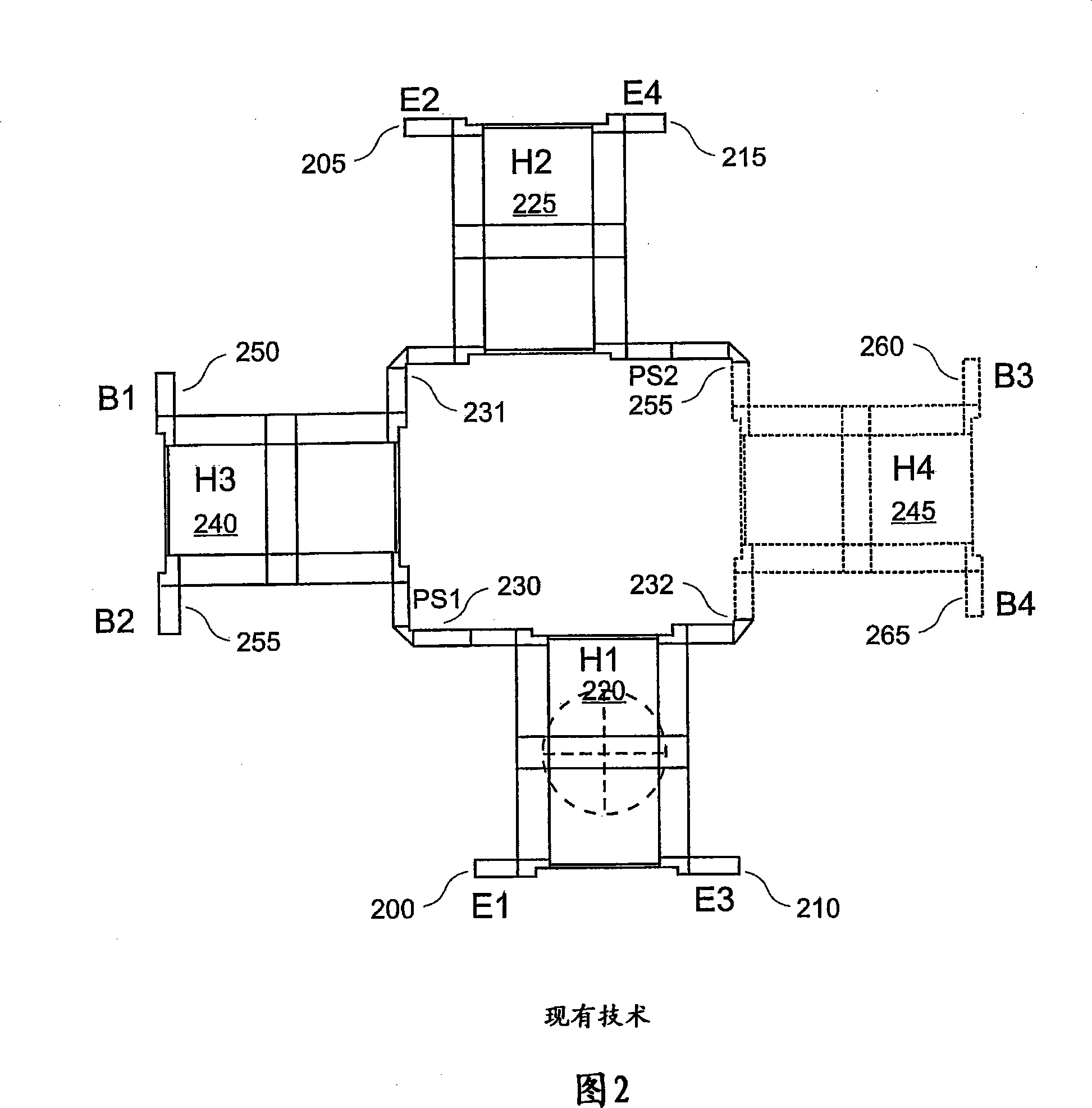
[0049] [47] Electrically, the Butler matrix in Fig. 3 is identical to the Butler matrix in Fig. 2. The main difference is the inwardly facing positioning of the beam ports 350, 355, 360 and 365, and the resulting change in the length of the phase shifters 330, 335 and connectors 331, 332.
[0050] [48] The inward-facing positioning of the beam ports enables beam port pairs B1 350 and B3 360 and B2...
PUM
 Abstract
Description
Claims
Application Information