Ethernet transmission method and Ethernet transmitting/receiving device based on coaxial cable network
A technology of a transceiver device and a transmission method is applied in the field of Ethernet physical layer transmission to achieve the effects of low cost and signal distortion elimination.
Active Publication Date: 2010-12-01
NEW H3C TECH CO LTD
View PDF0 Cites 0 Cited by
- Summary
- Abstract
- Description
- Claims
- Application Information
AI Technical Summary
Problems solved by technology
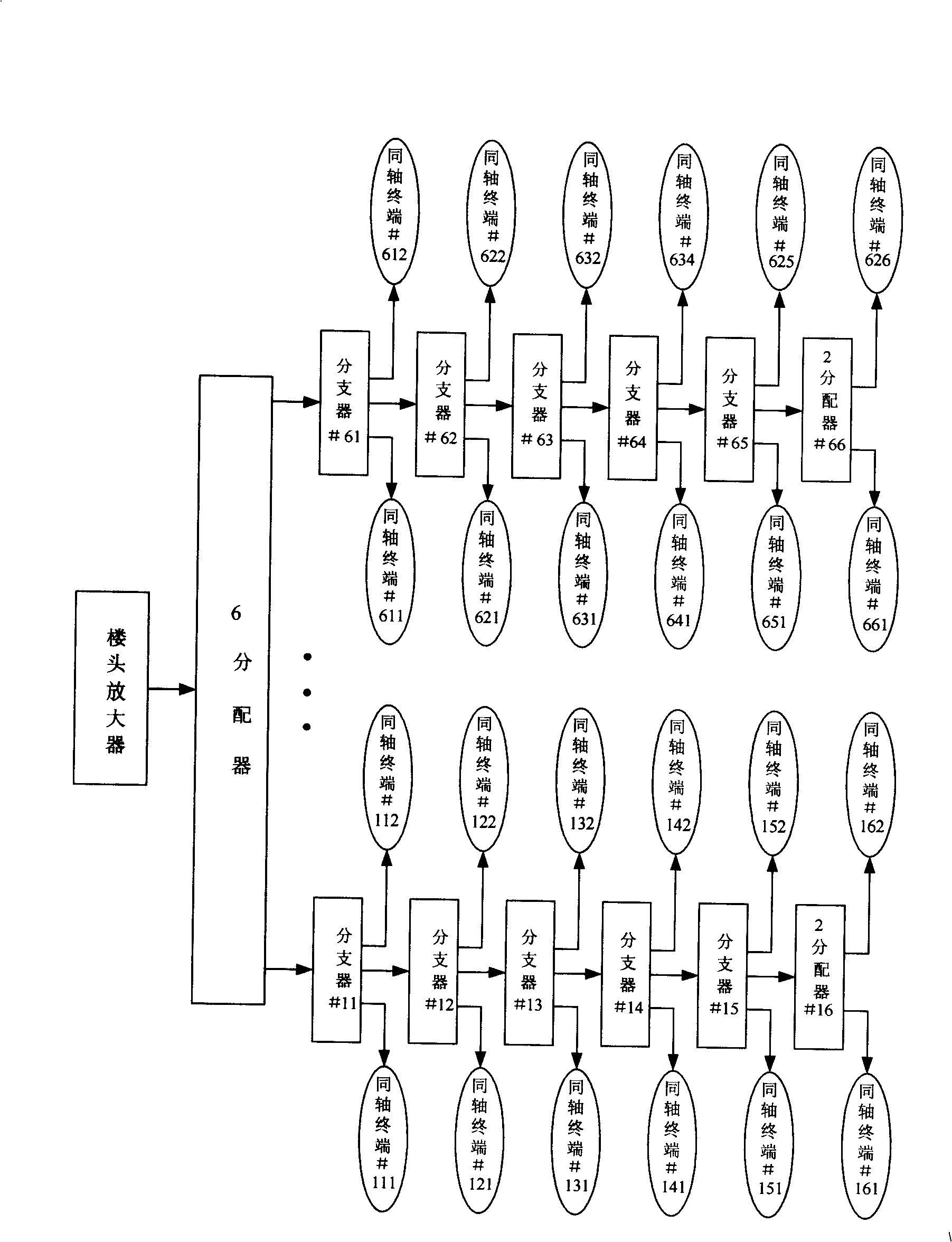
For the transmission problem of the above-mentioned physical layer signal that needs to be solved, the purpose of the present invention is to utilize the existing coaxial tree network to transmit the baseband signal of Ethernet, by transforming the transceiver devices of the sending side and the receiving side physical layer, so as to achieve Support baseband Ethernet for point-to-multipoint, large attenuation transmission on the existing TV coaxial network
Method used
View moreImage
Smart ImageViewing Examples

Examples
Embodiment 1
Embodiment 2
Login to View More PUM
 Abstract
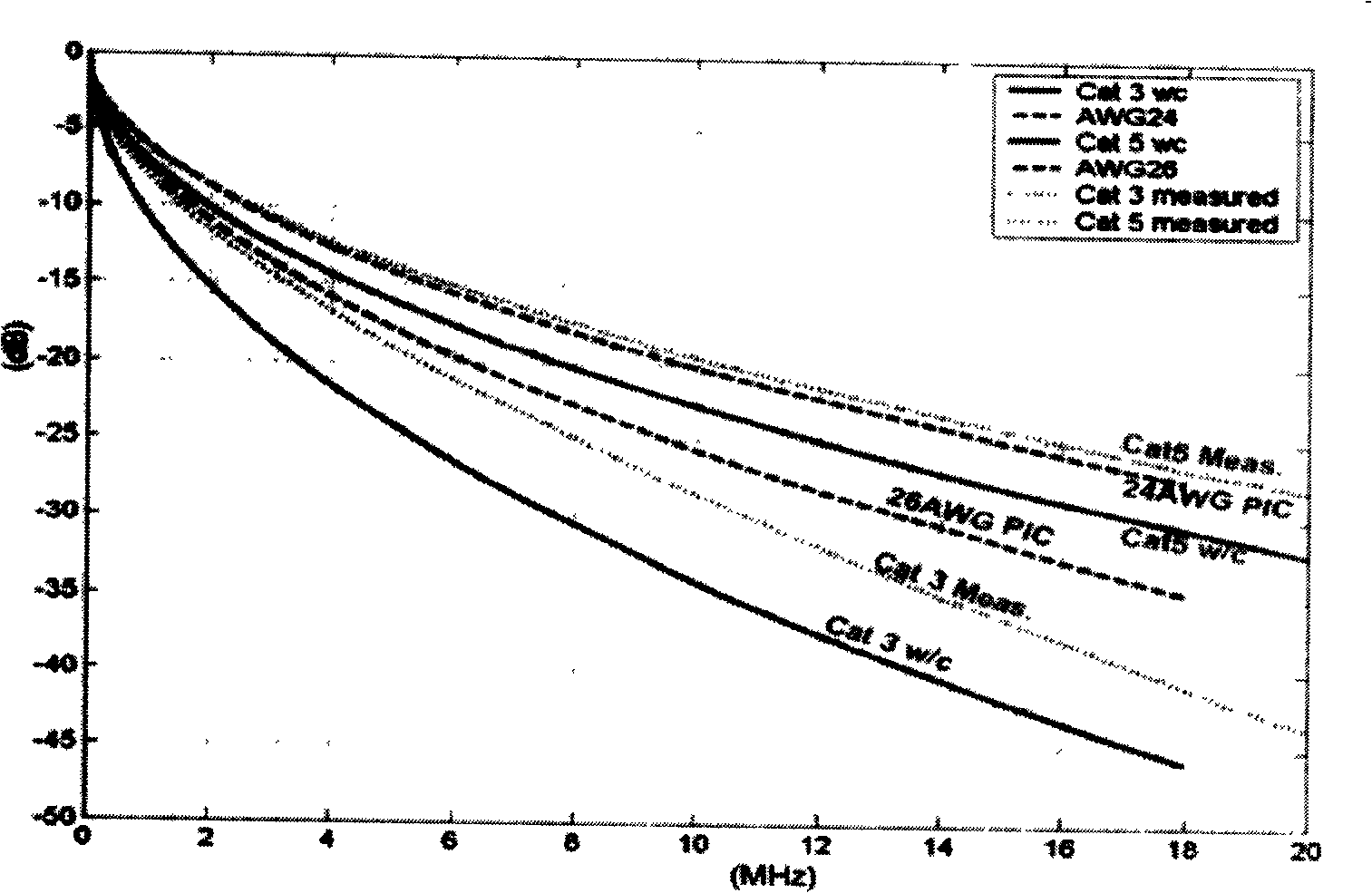
The invention relates to an ethernet tranceiving device on the basis of a coaxial cable network and a method for transmitting the Ethernet, the receiving device comprises an analog interface (110) which is connected with a coaxial cable, a voltage amplification unit (260) which is connected with the analog interface (110) and used to amplify sent signal electric levels of the analog interface (110), a receiving unit (200) which is connected with the analog interface (110), wherein the receiving unit (200) comprises a receiving and amplifying unit (210) which is used to amplify received signalelectric levels form the analog interface (110), wherein the magnification factors of the voltage amplification unit (260) and the receiving and amplifying unit (210) are confirmed by attenuation characteristics parameters of a coaxial cable distributing network. The method for transmitting comprises: amplifying service signals before sending services and amplifying the service signals on the direction of receiving the services. The invention can realize that baseband electrical signals of the ethernet are transmitted in a coaxial distributing network and the cost is low.
Description
Ethernet transceiver device and Ethernet transmission method based on coaxial cable network technical field The present invention relates to Ethernet physical layer transmission technology, in particular to an Ethernet transceiver device and an Ethernet transmission method based on a coaxial cable network; specifically, to an Ethernet transceiver device based on a cable television coaxial cable distribution network, and The physical layer transmission method of Ethernet over coaxial cable distribution network. Background technique In the existing cable TV fiber coaxial network (HFC), the TV program is transmitted from the front end to the optical node of the TV network close to the user through the optical fiber (generally, an optical node covers 300 to 500 users in the surrounding area). After the optical signal is converted into an electrical signal at the node, the TV signal is transmitted to each resident's home through the residential building through the coaxial cabl...
Claims
Login to View More Application Information
Patent Timeline
 Patent Type & Authority Patents(China)
IPC IPC(8): H04L12/02H04L12/28H04B3/00
Inventor 于洋
Owner NEW H3C TECH CO LTD
Features
- R&D
- Intellectual Property
- Life Sciences
- Materials
- Tech Scout
- Unparalleled Data Quality
- Higher Quality Content
- 60% Fewer Hallucinations
Learn More Browse by: Latest US Patents, China's latest patents, Technical Efficacy Thesaurus, Application Domain, Technology Topic, Popular Technical Reports.
© 2025 PatSnap. All rights reserved.Legal|Privacy policy|Modern Slavery Act Transparency Statement|Sitemap|About US| Contact US: help@patsnap.com