
Method and apparatus for compensating signal distortion caused by noise

a signal distortion and compensation technology, applied in the field of compensating signal distortion caused by noise, can solve the problems of deteriorating the picture quality of an image, generating fixed pattern noise, adding variable noise, etc., and achieve the effect of improving picture quality

Inactive Publication Date: 2012-04-17
SAMSUNG ELECTRONICS CO LTD
View PDF3 Cites 0 Cited by
  • Summary
  • Abstract
  • Description
  • Claims
  • Application Information

AI Technical Summary

Benefits of technology

The present invention provides an apparatus and method for improving picture quality by compensating for signal distortion caused by noise. The apparatus includes a noise reduction unit and a signal compensator. The noise reduction unit reduces noise in an input signal, while the signal compensator compensates the output signal of the noise reduction unit to remove signal distortion caused by non-zero mean random noise. The method involves reducing noise of an input signal and compensating it to remove signal distortion caused by non-zero mean random noise. The technical effect of this invention is to improve the quality of pictures and videos captured by imaging devices.

Problems solved by technology

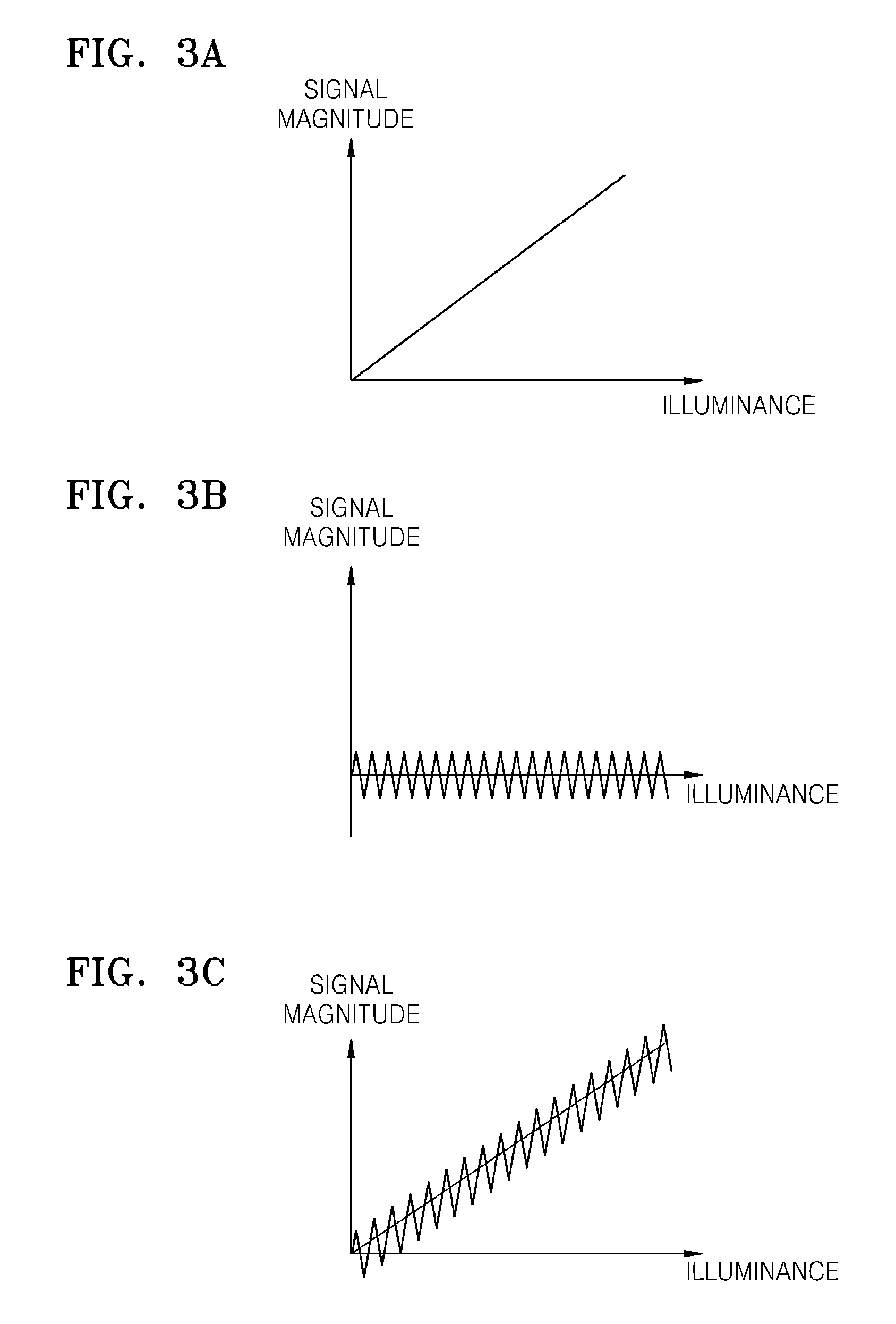
An imaging device is required to generate an electric signal ideally proportional to the illuminance of light input thereto; however, various noise is added when the light is converted into the electric signal.
Dark current noise is thermal noise proportional to temperature and deteriorates the picture quality of an image when the image is obtained with a low illuminance. kTC noise is generated according to various switching pulse signals used to drive a CMOS camera or a CCD camera.
Fixed pattern noise is generated when a CMOS imaging device or a CCD imaging device includes a defect pixel.
The fixed pattern noise is caused by non-uniformity generated due to various causes in a CMOS manufacturing process or a CCD manufacturing process and appears as white spot defect, black spot defect, line defect, banded spot defect and sensitive speck.
The aforementioned noise is added to charges photo-electric-converted by an imaging device and accumulated to deteriorate picture quality.
Referring to FIG. 7, a small dynamic range and a relatively high noise level compared to the magnitude of a signal at a low illuminance become problems in the imaging device.
However, when the image-capturing environment is dark, noise such as fixed pattern noise, dark current noise and kTC noise become relatively larger compared to the quantity of charges photo-electric-converted by the imaging device and accumulated, and thus picture quality is severely deteriorated.

Method used


Image

  • Method and apparatus for compensating signal distortion caused by noise
  • Method and apparatus for compensating signal distortion caused by noise
  • Method and apparatus for compensating signal distortion caused by noise

Examples


Embodiment Construction

[0031]The present invention will now be described more fully with reference to the accompanying drawings, in which exemplary embodiments of the invention are shown. The invention may, however, be embodied in many different forms and should not be construed as being limited to the exemplary embodiments set forth herein; rather, these exemplary embodiments are provided so that this disclosure will be thorough and complete, and will fully convey the concept of the invention to those skilled in the art. Throughout the drawings, like reference numerals refer to like elements.

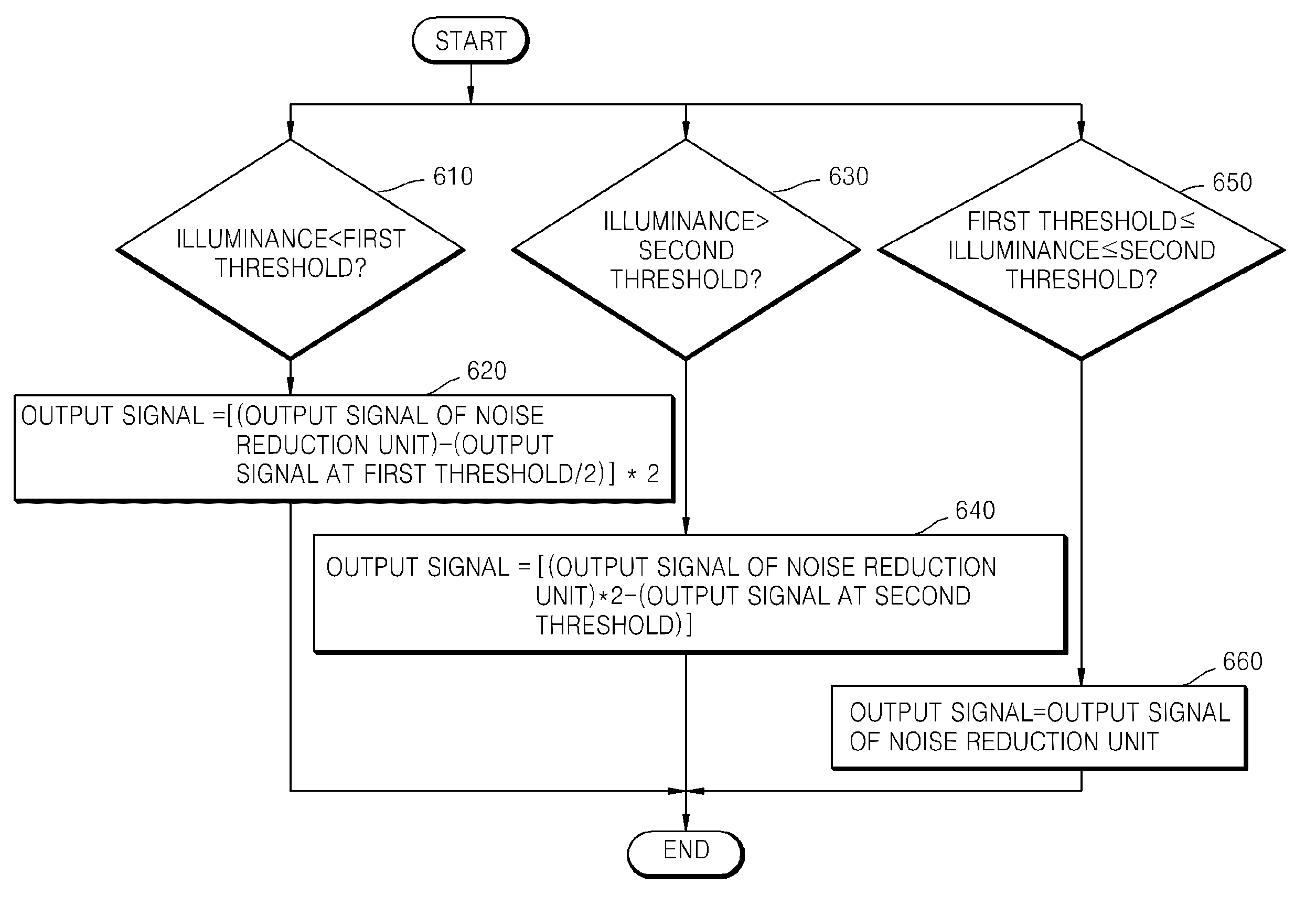
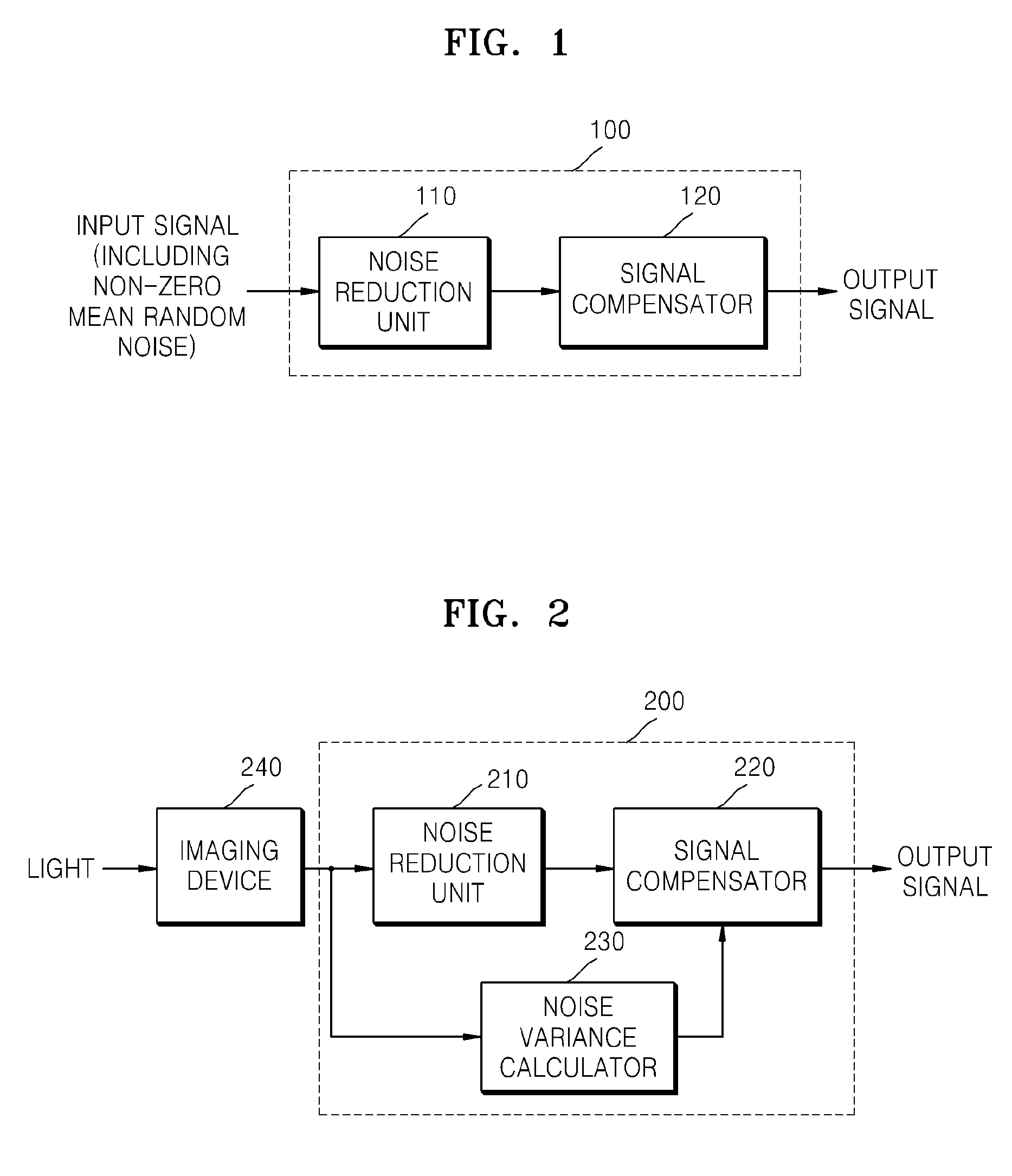
[0032]FIG. 1 is a block diagram of an apparatus 100 for compensating signal distortion caused by noise, according to an exemplary embodiment of the present invention. Referring to FIG. 1, the apparatus 100 for compensating signal distortion caused by noise according to the current exemplary embodiment of the present invention includes a noise reduction unit 110 and a signal compensator 120. An input signal of the noi...


PUM


Abstract

Provided are an apparatus and a method for compensating signal distortion caused by noise. The apparatus comprises a noise reduction unit which reduces noise of an input signal including non-zero mean random noise, and a signal compensator which compensates the output signal of the noise reduction unit so that a signal distortion due to the non-zero mean random noise is removed from the output signal of the noise reduction unit.

Description

CROSS-REFERENCE TO RELATED PATENT APPLICATION[0001]This application claims priority from Korean Patent Application No. 10-2007-0068800, filed on Jul. 9, 2007 in the Korean Intellectual Property Office, the disclosure of which is incorporated herein in its entirety by reference.BACKGROUND OF THE INVENTION[0002]1. Field of the Invention[0003]Methods and apparatuses consistent with the present invention relate to compensating signal distortion caused by noise and, more particularly, to compensating signal distortion caused by non-zero mean random noise of an imaging device to improve picture quality.[0004]2. Description of the Related Art[0005]Imaging devices convert light into an electric signal corresponding to an image, and include complementary metal oxide semiconductor (CMOS) imaging devices and charge coupled device (CCD) imaging devices. An imaging device is required to generate an electric signal ideally proportional to the illuminance of light input thereto; however, various n...

Claims


Application Information

Patent Timeline
Patent Type & Authority Patents(United States)
IPC IPC(8): H04N5/217H04N5/235H04N5/21H04N23/76H04N25/00
CPCH04N5/357H04N25/618H04N25/60
Inventor KIM, IL-DOJUN, JAE-SUNGCHOI, BYUNG-SUN
Owner SAMSUNG ELECTRONICS CO LTD
Learn More