Overflow shutoff valve for liquefied gas container

A technology of gas storage tanks and stop valves, which is applied in gas/liquid distribution and storage, lift valves, safety valves, etc. It can solve the problems of prolonged recovery time, deterioration of the safety and reliability of gas storage tanks, and increased manufacturing costs. Achieve the effect of shortening recovery time, shortening gas refill time and preventing overflow

Active Publication Date: 2008-07-23
申一换
View PDF1 Cites 7 Cited by
  • Summary
  • Abstract
  • Description
  • Claims
  • Application Information

AI Technical Summary

Problems solved by technology

[0006] However, the prior art shown in FIG. 8 has the following disadvantages: in order to recover the residual gas in the gas storage tank (gas bomb) that has run out of gas storage so as to refill the gas storage tank with gas, its recovery time and refilling too long
Moreover, the gas cut-off valve 100B shown in FIG. 9 has the following several disadvantages: the recovery time is prolonged when the residual gas in the gas storage tank is recovered, and the spring 380 for supporting the ball 370 cannot return to it after the gas is refilled. initial position of
In addition, after refilling is completed, when the rebound force of the upper and lower springs 480 and 490 makes the disc 460 and the valve plate 470 return to their initial positions, the lower end of the protrusion 431 will not clamp the upper surface of the spherical valve plate 470. , but the lower end of the protrusion 431 will catch the periphery of the disc 460 with a planar upper surface, therefore, it deteriorates the safety and reliability of the gas storage tank in use
[0015] Meanwhile, the cylinder of each conventional gas shut-off valve has a single-layer structure, so the cylinder has the following problems: Since many materials are required and the processing expense increases, the manufacturing cost increases

Method used


Image

  • Overflow shutoff valve for liquefied gas container
  • Overflow shutoff valve for liquefied gas container
  • Overflow shutoff valve for liquefied gas container

Examples


Embodiment Construction

[0033] Reference will now be made in detail to the preferred embodiments of the invention, examples of which are illustrated in the accompanying drawings.

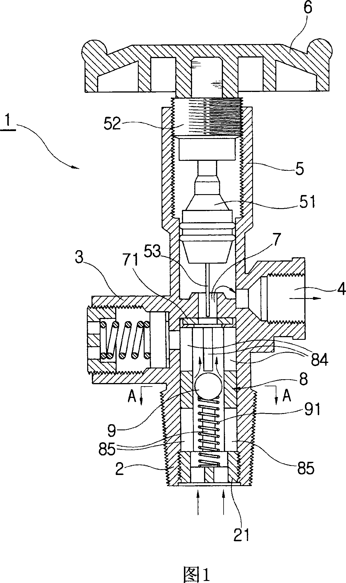
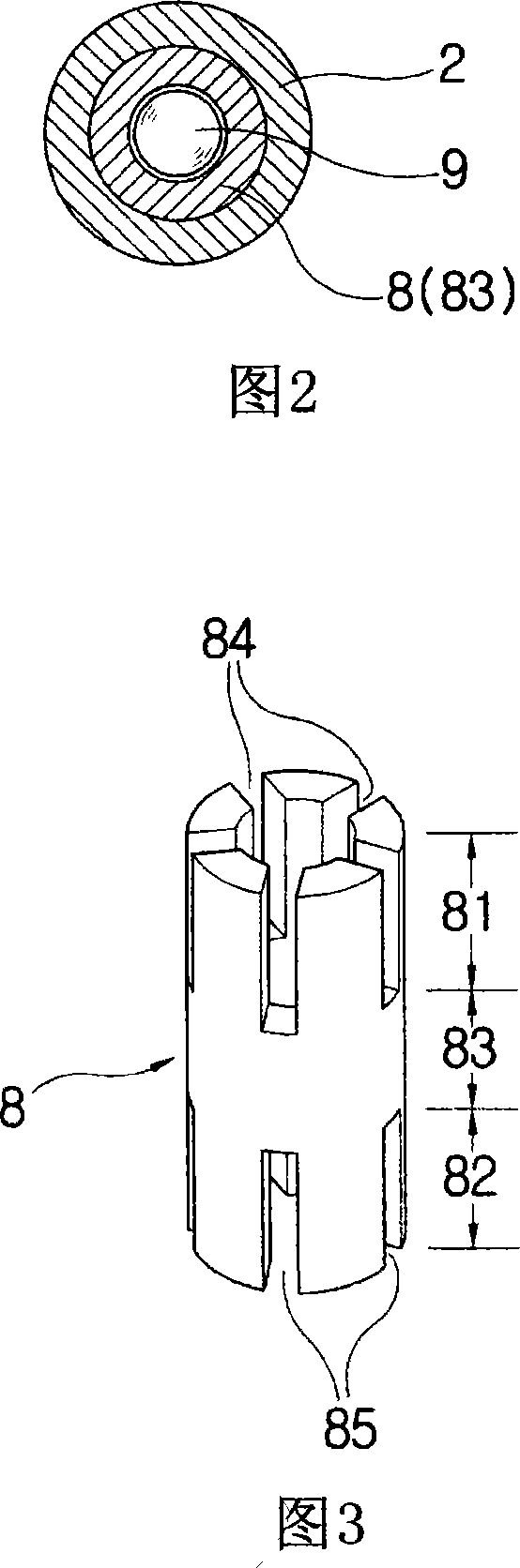
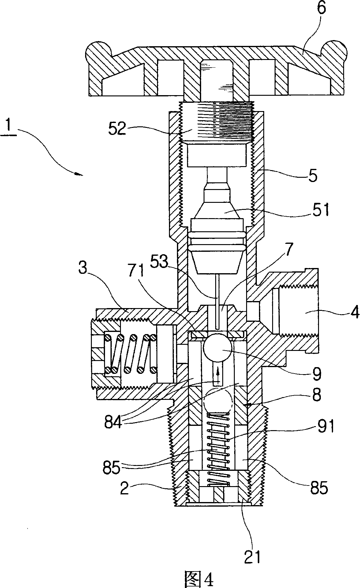
[0034] Fig. 1 is a sectional view showing the operation state of triggering the overflow stop valve when the gas is normally supplied, Fig. 2 is a sectional view along the line A-A of Fig. The perspective view of the cylinder above, Figure 4 is a cross-sectional view showing the state of triggering the overflow stop valve to interrupt the gas flow when the gas overflows, Figure 5 is a cross-sectional view showing the state of the overflow stop valve when the gas is recovered Operating state, FIG. 6 is a sectional view showing the operating state of the overflow stop valve when the gas tank is refilled with gas, and FIG. 7 is a sectional view along line B-B of FIG. 6 .


PUM


Abstract

Disclosed herein is an over-flow shutoff valve for a liquefied petroleum gas container The overflow shutoff valve includes: a gas inlet mounted at the gas container; a safety valve protrudingly formed at one side of the upper portion of the gas inlet for discharging the internal pressure of the gas container when the internal pressure is rapidly increased; a gas outlet protrudingly formed at the other side of the upper portion of the gas inlet for supplying gas to a gas appliance; a valve handle for vertically controlling a valve stem mounted on a controlling part protruding from the upper portion of the gas inlet; a gas inflow and outflow hole located between the gas inlet and the controlling part for allowing inflow and outflow of the gas; a cylinder fit into the inner circumference of the gas inlet; and a ball positioned inside the cylinder, the cylinder and the ball being adapted to normally discharge the gas contained in the gas container and regulate a gas flow to prevent an excessive outflow of the gas, wherein the cylinder has an upper part, a lower part and an intermediate part between the upper and lower parts, each of which has the same thickness, and is made of a hollow pipe, the upper part having a plurality of upper incised slots of a uniform length vertically formed on the circumference thereof in an axial direction in such a manner as to be spaced apart from one another at regular intervals and be opened upwardly, and the lower part having a plurality of lower incised slots of a uniform length vertically formed on the circumference thereof in the axial direction in such a manner as to be spaced apart from one another at regular intervals and be opened downwardly.

Description

technical field [0001] The present invention relates to an overflow shut-off valve for a liquefied petroleum gas storage tank, on which a cylinder of improved structure is mounted so that the gas is normally supplied, the gas flow is automatically interrupted when the gas is excessively released abnormally, and the gas storage is shortened The recovery time of the residual gas stored in the gas tank is recovered before the tank is refilled with gas, and the refill time of the gas tank is shortened. Background technique [0002] Generally, the relevant rules stipulate that the LPG gas storage tank should be equipped with an overflow stop valve, which is used for normal supply of gas, and when gas heating appliances (such as gas stoves, gas boilers, etc.) discharge gas excessively or when due to use When the gas supply hose is abnormal and the gas is discharged excessively, the gas is automatically interrupted. [0003] Conventional gas stop valves are disclosed in Korean Pat...

Claims


Application Information

Patent Timeline
Patent Type & Authority Applications(China)
IPC IPC(8): F17C13/04
CPCF17C2201/0109F17C2205/0332F16K17/285F17C2205/0394F17C2223/0153F17C13/04F17C2250/0636F16K1/306F17C2221/035F17C2223/033F17C2205/0385F17C2205/0329Y10T137/7756
Inventor 申一换
Owner 申一换
Why Eureka
Try Eureka