Insulation resistance degradation detector and failure self-diagnostic method for insulation resistance degradation detector

A technology of insulation resistance and voltage detectors, applied in the direction of measuring resistance/reactance/impedance, very high resistance measurement, instruments, etc., can solve the problems of not being able to sense insulation resistance faults, increasing the number of components in the circuit, etc.

Inactive Publication Date: 2008-07-23
TOYOTA JIDOSHA KK
View PDF2 Cites 31 Cited by
  • Summary
  • Abstract
  • Description
  • Claims
  • Application Information

AI Technical Summary

Problems solved by technology

[0005] However, with the configuration of the insulation resistance drop detector disclosed in Patent Document 1, failure of the insulation resistance drop detector itself cannot be sensed
[0006] In addition, with the insulation resistance decrease detector disclosed in Patent Document 2, for the fault self-diagnosis function as a function of detecting its own fault, a low-pass filter is required, which increases the number of components constituting the circuit

Method used


Image

  • Insulation resistance degradation detector and failure self-diagnostic method for insulation resistance degradation detector
  • Insulation resistance degradation detector and failure self-diagnostic method for insulation resistance degradation detector
  • Insulation resistance degradation detector and failure self-diagnostic method for insulation resistance degradation detector

Examples


no. 1 example

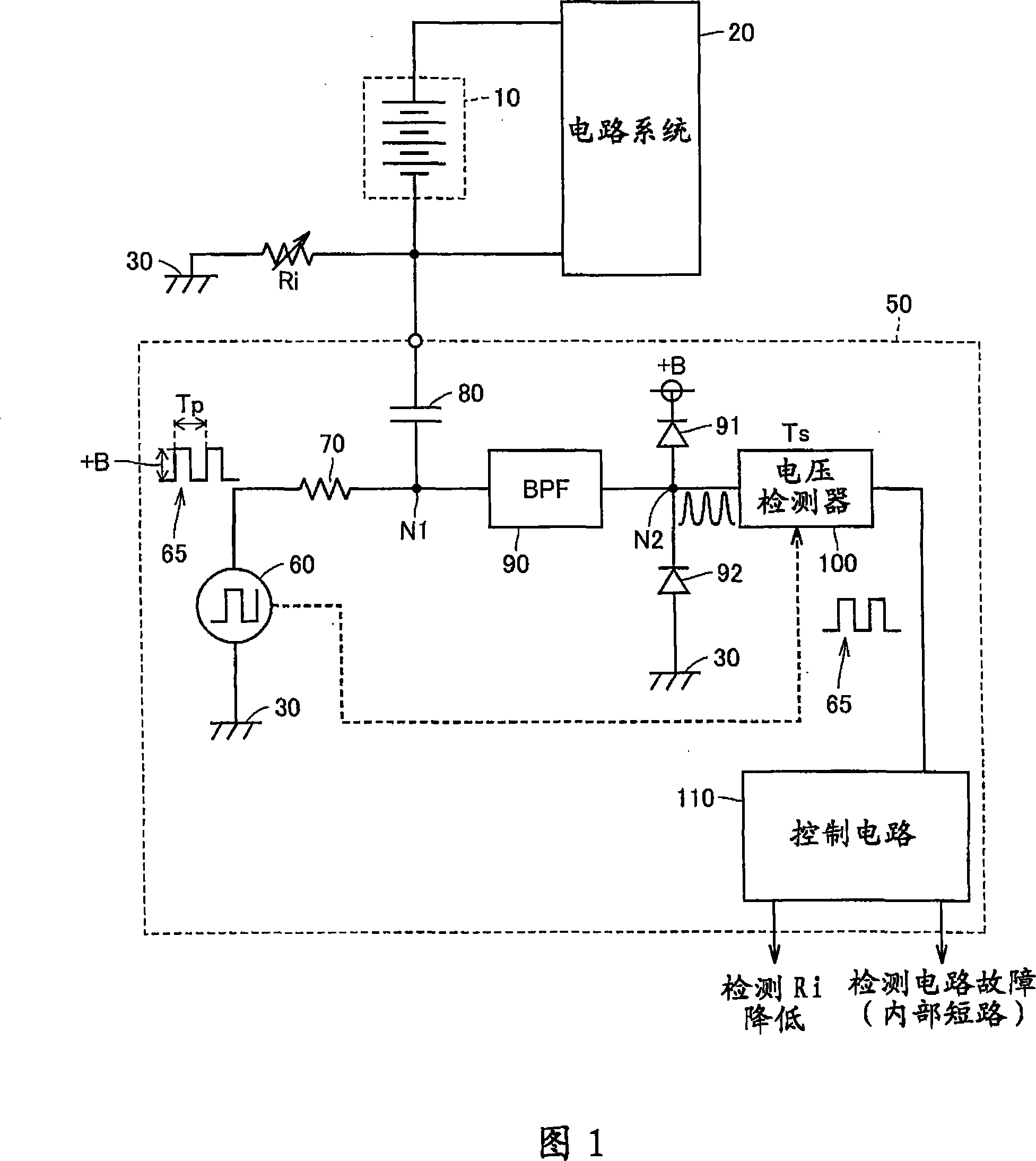
[0035] Referring to FIG. 1 , an insulation resistance decrease detector 50 according to a first embodiment of the present invention detects a decrease in insulation resistance Ri with respect to a ground 30 of a DC (direct current) power supply 10 . To the DC power supply 10, a circuit system 20 that supplies a power supply voltage from the DC power supply 10 to operate is connected. The DC power supply 10 is an electric energy storage device such as a secondary battery, a fuel cell, or a capacitor, which is integrated in an electric vehicle, a hybrid vehicle, or the like as a motor power supply to drive the vehicle.

[0036] In the example of such a vehicle, ground 30 corresponds to said body. If the insulation resistance Ri decreases, a person touching the vehicle body 30 may get an electric shock, and therefore, detecting a decrease in the insulation resistance Ri is very critical from a safety point of view. Therefore, it is necessary not only to detect a decrease in the ...

no. 2 example

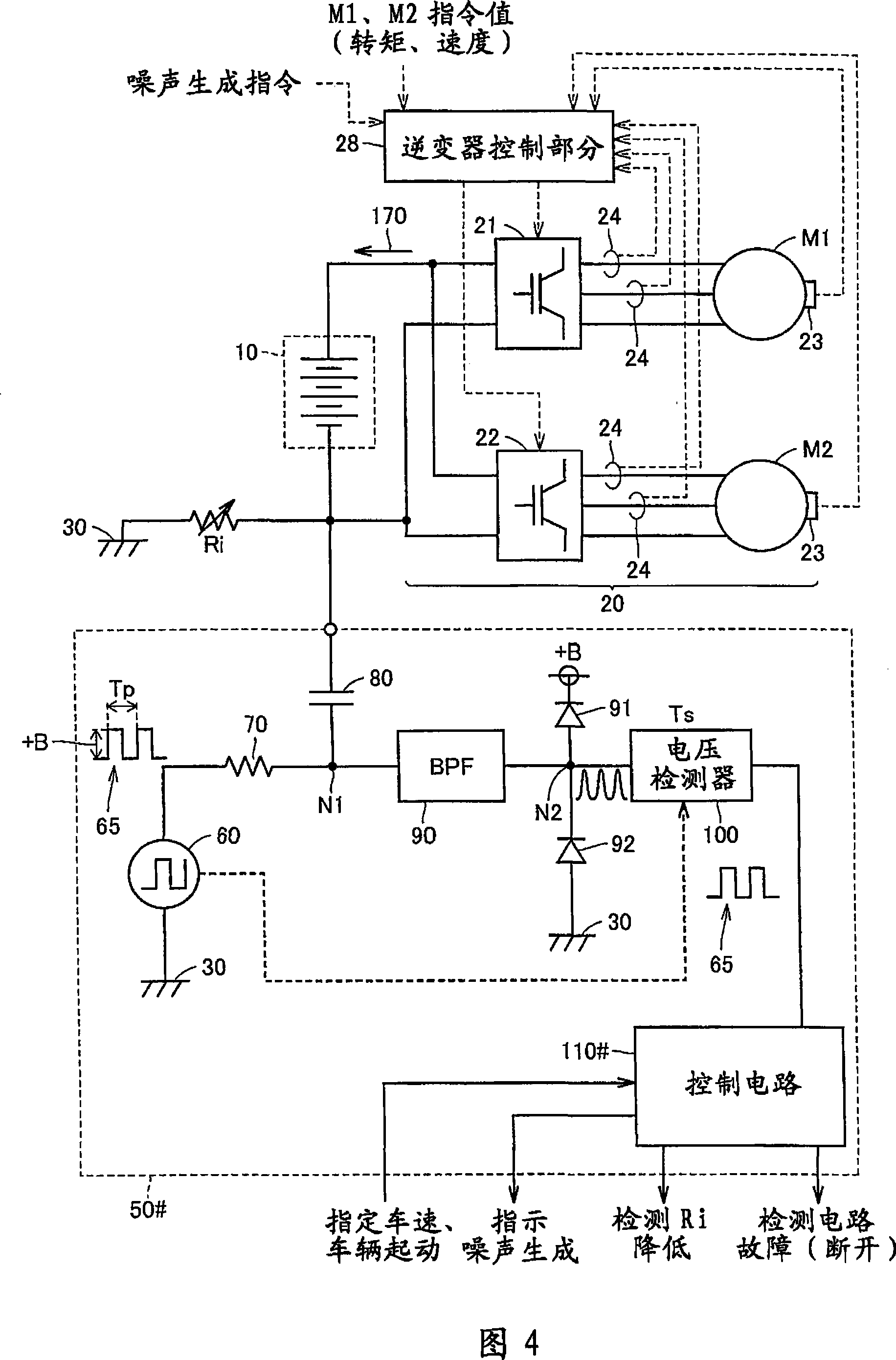
[0055] In the second embodiment, a configuration is described in which, by an insulation resistance decrease detector having a circuit configuration similar to that in the first embodiment, it is possible to sense whether there is leakage between the power supply 10 and the coupling capacitor 80 to be sensed. disconnection fault.

[0056] FIG. 4 is a block diagram showing the configuration of insulation resistance decrease detector 50# according to the second embodiment of the present invention.

[0057] Referring to FIG. 4 , for comparison, the insulation resistance decrease detector 50 # differs from the insulation resistance decrease detector 50 shown in FIG. 1 in that instead of the control circuit 110 , it is equipped with a control circuit 110 #. Similar to the control circuit 110, the operation of the control circuit 110# is generally processed in a software-like manner using a microcomputer or the like. Therefore, insulation resistance drop detector 50# shown in FIG. ...


PUM


Abstract

An insulation resistance reduction detector (50), comprising a pulse generator (60), which applies a pulse signal (65) to a series circuit in which a detection resistor (70), a coupling capacitor (80) and an insulation resistance (Ri) are connected in series ). In the state where the pulse signal (65) is applied to the series circuit, the control circuit (110) detects the pulse-shaped divided voltage appearing at the node (N1) through the voltage detection circuit (100) through the band-pass filter (90) , thereby sensing a decrease in insulation resistance (Ri). Further, when the voltage detected by the voltage detection circuit (100) is maintained at least a specified voltage over a number of cycles of the pulse signal (65), the control circuit (110) senses that the insulation resistance decrease detector itself failure. In this way, an insulation resistance drop detector with a fault self-diagnosis function is realized with a simple configuration.

Description

technical field [0001] The present invention relates to an insulation resistance reduction detector and a fault self-diagnosis method thereof, in particular to a fault self-diagnosis function for sensing a fault of the insulation resistance reduction detector itself. Background technique [0002] A power source insulated from a ground, for example, a battery (DC power source) installed in a vehicle such as an automobile (the ground corresponds to the vehicle) must be equipped with a device for detecting a decrease in insulation resistance between the power source and the ground circuit. [0003] As such an insulation resistance drop detector, Japanese Patent Laid-Open No. 10-290529 (hereinafter referred to as Patent Document 1) discloses a configuration of an insulation resistance drop detector applied to an electric vehicle having a high voltage power supply. [0004] Japanese Patent Laid-Open No. 2005-114496 (hereinafter referred to as Patent Document 2) discloses a confi...

Claims


Application Information

Patent Timeline
Patent Type & Authority Applications(China)
IPC IPC(8): G01R27/02G01R35/00G01R31/50
CPCG01R27/025G01R31/12G01R31/1263G01R31/52G01R31/50
Inventor 内田健司
Owner TOYOTA JIDOSHA KK
Why Eureka
Try Eureka