
Piercing mandrel of automatic dotter and automatically dotting method

A punch, automatic technology, used in clothing, footwear, tools for sewing clothes, etc., to ensure one-time success, smooth surface, and ensure accuracy

Inactive Publication Date: 2008-07-30
杭州中凌广告器材有限公司
View PDF4 Cites 9 Cited by
  • Summary
  • Abstract
  • Description
  • Claims
  • Application Information

AI Technical Summary

Problems solved by technology

In practice, due to the influence of many factors such as its material and elasticity on the flexible support pad in the punching hole of the make-up groove rail, the punch cannot make the make-up on the flexible support pad completely contact with the flexible support pad at the same time. Separation, accurate combination with the accurate punching of the lower button, so the button failure is inevitable

Method used


Image

  • Piercing mandrel of automatic dotter and automatically dotting method
  • Piercing mandrel of automatic dotter and automatically dotting method
  • Piercing mandrel of automatic dotter and automatically dotting method

Examples


Embodiment 1

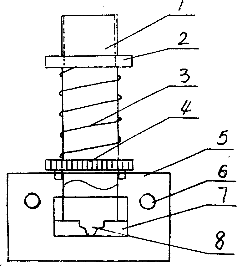
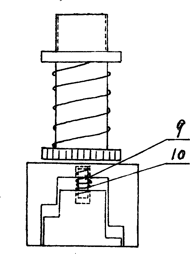
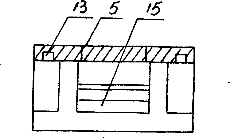
[0012] Embodiment 1: with reference to attached Figure 1~4 . The automatic buckle punch includes a punch base. The structure of the punch base has been disclosed in the background art, and its manufacturing process is a prior art, so it will not be described here. The punch jacket 5 has a groove structure and is made by a wire cutting machine. The two punch chucks 7 are made by a wire cutting machine and are located in the groove of the punch jacket 5. The two punch clips located in the groove of the punch jacket 5 are The head 7 adopts the pin shaft 6 to be pinned to the two side plates of the punch jacket 5 respectively and the two punch chucks 7 rotate around the pin shaft 6. The upper end of the punch chuck is in conflict with the inner end surface of the punch jacket, which is convenient for the punch chuck to be opened downward. The ends of the chucks 7 of the two punches are opposite to the inner end surface of the punch jacket 5 with a guide column hole 13, the guid...

Embodiment 2

[0013] Embodiment 2: The automatic buckle method of the punch of the automatic buckle machine, the lower buckle is located on the punch base, the material to be buckled is located on the lower buckle, and the bottom of the jacket has been flattened and punched when the punch moves down to the workpiece The surface of the material makes the surface smooth when punching and buckling, and there will be no folding and shrinking. The buckle enters the punching socket formed by the two punch chucks through the button hole on the back of the punch jacket, and the piston in the cylinder drives the punching When the rod moves downward, the punch located at the lower end of the punch rod passes through the hole of the make-up button, and at the same time directly impacts the make-up and the punching socket formed by the two punch chucks, the punching socket is forced to open automatically, and the upper button is automatically opened. The buckle falls steadily on the material to be punch...


PUM


Abstract

The invention relates to an automatic dotter punch for advertisement lamp box, tent, tent cloth and toy product and the dotting method thereof; a lower buckle is positioned on a base of the punch, the dotted material is positioned on a lower buckle, the upper buckle enters the punch buckle supporting port formed by two punch grips via a buckle inlet hole on the back of a punch sleeve, a piston in an air cylinder drives a punch rod to move up and down; when passing through an upper buckle hole, the punch positioned at the lower end of the punch rod directly impacts the upper buckle and the punch buckle supporting port formed by two punch grips; the punch buckle supporting port is forced to open automatically; the upper buckle stably falls on the dotted material, and the upper buckle is punched and combined with the lower buckle positioned at the bottom of the material, and thus dotting is finished. After the dotting is finished, the punch and the punch buckle supporting port automatically reset under the functions of the recovery of the air cylinder and the spring.

Description

technical field [0001] The invention relates to a punch and a buttoning method of an automatic buttoning machine for advertising light boxes, tents, tarpaulins and toy products, belonging to the field of buttoning machine component assembly manufacturing. Background technique [0002] The applicant's patent application number 200510083406.1, titled "automatic buckle machine delivery buckle method", in which the upper buckle of the automatic buckle machine is set on the upper buckle guide rod, and the lower buckle falls into the lower buckle groove rail through the buckle drop mechanism. The upper and lower button push rods move synchronously under the push of the cylinder piston rod, and the upper button push rod pushes the upper button sleeved at the bottom of the upper button guide rod to slide over the ball head at the bottom end of the upper button guide rod and transport the upper button to the upper button groove track At the same time as the punched flexible support p...

Claims


Application Information

Patent Timeline
Patent Type & Authority Applications(China)
IPC IPC(8): A41H37/02A43D100/10
Inventor 凌正然
Owner 杭州中凌广告器材有限公司
Learn More