Eureka AIR delivers breakthrough ideas for toughest innovation challenges, trusted by R&D personnel around the world.

Safety injector core bar lockup device

A technology for a safety syringe and a locking device, which is applied in the field of a safety syringe core rod locking device, can solve the problems of complex structure, difficult assembly, instability and the like, and achieves the effects of good safety performance, convenient use and reasonable structure

Inactive Publication Date: 2008-07-30
房东森
View PDF1 Cites 2 Cited by
  • Summary
  • Abstract
  • Description
  • Claims
  • Application Information

AI Technical Summary

Problems solved by technology

The disposable syringes currently in use belong to the concept of management, and are not "disposable" in terms of performance. They can be used repeatedly, leaving hidden dangers for cross-infection and easy to cause disease transmission.
Chinese patent 00205827.8 discloses a self-destructing safety syringe, which is composed of a syringe, a needle holder, a sealing ring, a rubber piston and a push rod. The sealing ring realizes airtightness, and the rear end of the needle seat is a puncture cone with a handle, which is easy to pierce the rubber piston membrane area at the end of the injection, and fits with the elastic collet at the front end of the push rod in the piston, and pulls the needle seat together with the injection needle into the syringe In this way, one-time use self-destruction can be achieved, but the structure is complex, assembly is difficult, the size of the components is strict, and the performance is not stable enough
However, the setting of the elastic locking parts is not reasonable enough, and it is easy to overturn during use, which is unstable and unreliable

Method used


Image

  • Safety injector core bar lockup device
  • Safety injector core bar lockup device
  • Safety injector core bar lockup device

Examples


Embodiment Construction

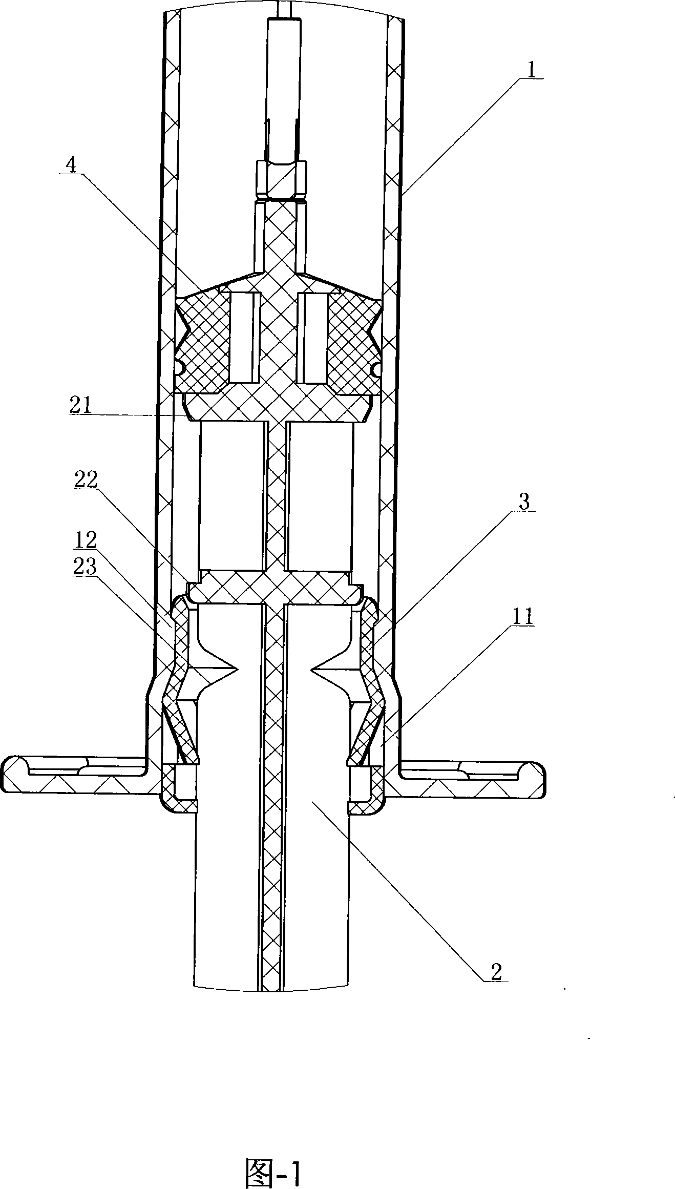
[0013] It can be seen from FIG. 1 that a plunger locking device for a safety syringe includes a casing 1 , a piston 4 , a plunger 2 and the like. The jacket is a hollow structure, and the core rod locking ring 3 is installed at the rear. The piston 4 is a good elastic body, which is installed and fixed on the front part of the core rod 2, and can move in the inner cavity of the jacket 1 to suck or inject medicinal liquid.

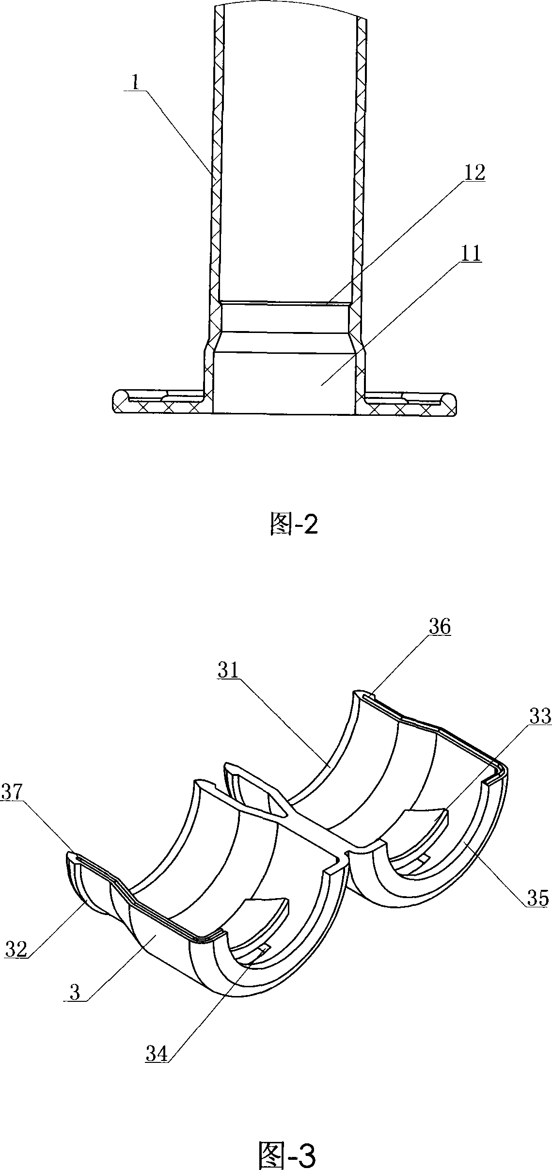
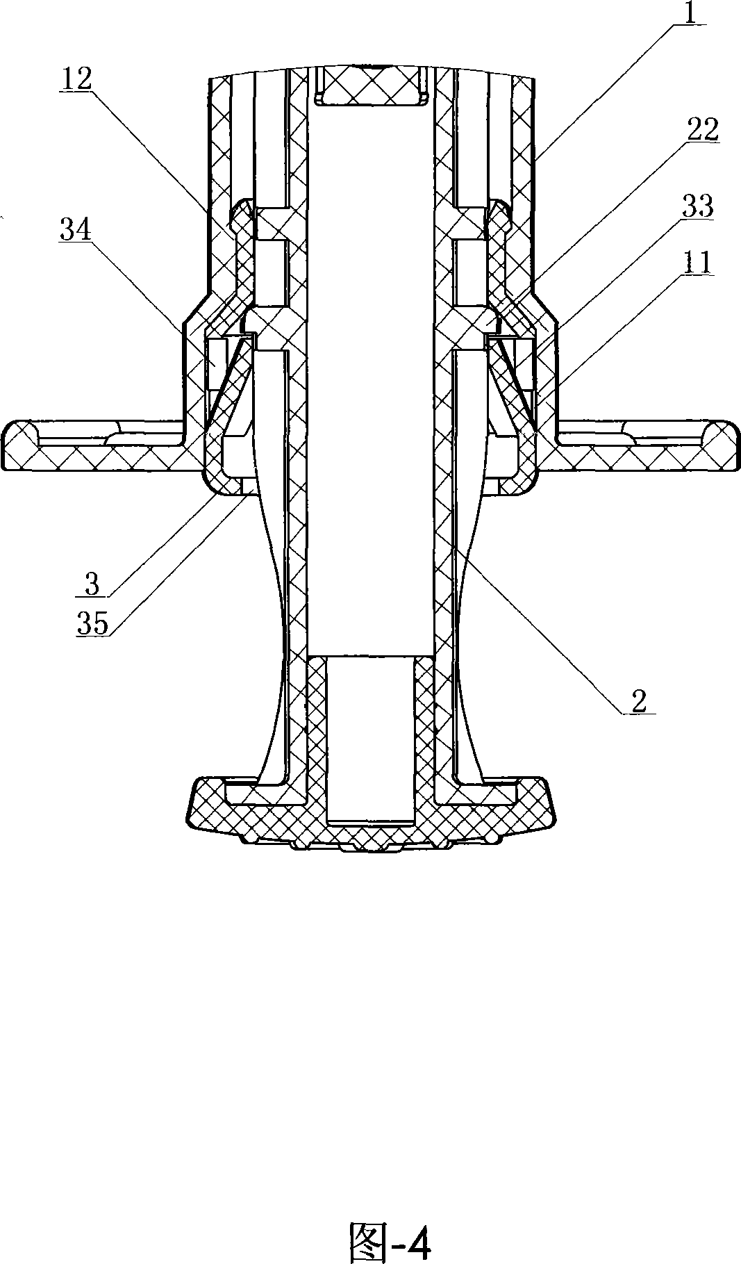
[0014] It can be seen from Fig. 1 and Fig. 3 that the core rod locking ring 3 is a through-cavity ring composed of two conjoined or split semicircular rings, on which two or more inwardly inclined elastic rings are provided. The damping claw 33, the tail end of the elastic damping claw is integrated with the wall of the core rod locking ring, and the wall of the core rod locking ring is provided with a recovery chamber 34 corresponding to the elastic damping claw, and the recovery chamber 34 is located in the core rod locking ring. Between 3 and coat 1. Co...


PUM


Abstract

The invention relates to a core pin locking device for a safety syringe, which comprises an outer sleeve, a piston and a core pin, wherein, the rear part of the outer sleeve is provided with a locking ring for the core pin which is a cavity through ring composed by two integrated or split semi-circular rings. An elastic damping claw which inclines inwards is arranged on the locking ring, the tail end of the elastic damping claw integrated with a wall body of the locking ring for the core pin as a whole; a positioning boss which is used for positioning by coordination with the elastic damping claw is correspondingly arranged on the core pin; an internal cavity at the front end of the locking ring for the core pin is provided with a concave arc face and a stop boss which is matched with the core pin is correspondingly arranged on the core pin. After the injection action of the invention is finished, the core pin when drawn back can drive a syringe head component to retract to the internal cavity of the outer sleeve, and then to the position of the locking ring for the core pin at the rear end of the outer sleeve; meanwhile, the core pin and the locking ring for the core pin coordinate for locking and the core pin fails to move forwards or backwards. The core pin locking device of the invention has reasonable structure, convenient and stable application and high safety as well as reasonability of the locking of the core pin, and can realize self-disposal after one-off injection.

Description

technical field [0001] The invention relates to a medical device, in particular to a safety syringe plunger locking device. Background technique [0002] We know that a syringe is a commonly used medical device. It generally includes a jacket, a piston, a core rod, and a needle. The disposable syringes currently in use belong to the concept of management, and are not "disposable" in terms of performance. They can be used repeatedly, leaving hidden dangers for cross-infection and easy to cause disease transmission. Chinese patent 00205827.8 discloses a self-destructing safety syringe, which is composed of a syringe, a needle holder, a sealing ring, a rubber piston and a push rod. The sealing ring realizes airtightness, and the rear end of the needle seat is a puncture cone with a handle, which is easy to pierce the rubber piston membrane area at the end of the injection, and fits with the elastic collet at the front end of the push rod in the piston, and pulls the needle se...

Claims


Application Information

Patent Timeline
Patent Type & Authority Applications(China)
IPC IPC(8): A61M5/50A61M5/315
CPCA61M5/502A61M5/322
Inventor 房东森
Owner 房东森
Why Eureka
Eureka Blog
Learn More