Electric control locking apparatus

An electric control lock and electric push rod technology, applied in the direction of roofs, building components, buildings, etc., can solve the problems of inability to control the ground, difficult hole alignment, small load, etc. Hole reliable effect

Inactive Publication Date: 2008-07-30
TONGJI UNIV
View PDF0 Cites 6 Cited by
  • Summary
  • Abstract
  • Description
  • Claims
  • Application Information

AI Technical Summary

Problems solved by technology

[0003] The purpose of the present invention is to provide an electronically controlled locking device suitable for large-scale institutions, which can overcome the shortcomings of existing locking devices such as difficulty in aligning holes, small load capacity and inability to operate on the ground

Method used


Image

  • Electric control locking apparatus
  • Electric control locking apparatus
  • Electric control locking apparatus

Examples


Embodiment Construction

[0025] The present invention will be further described below in conjunction with the embodiments shown in the accompanying drawings.

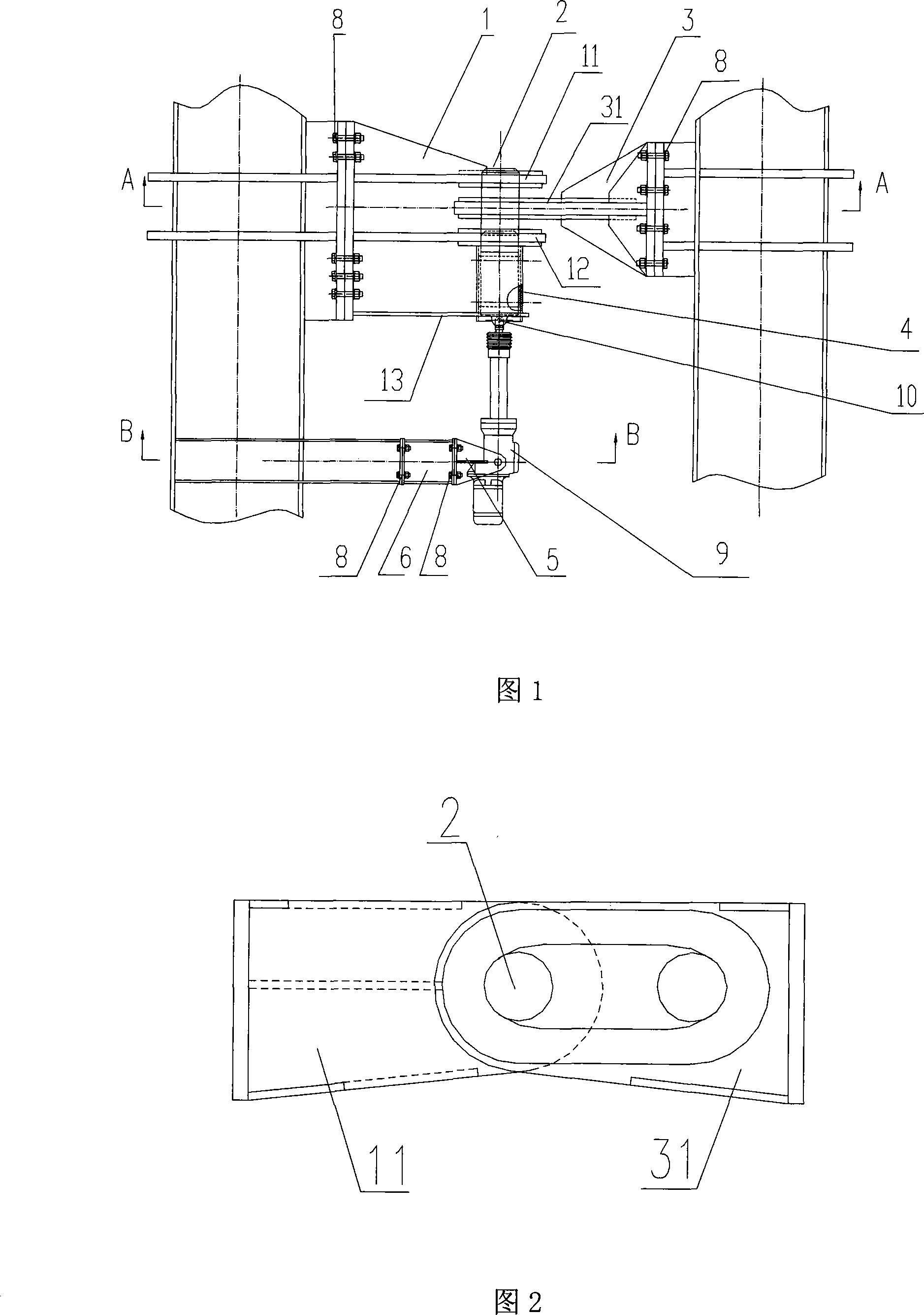
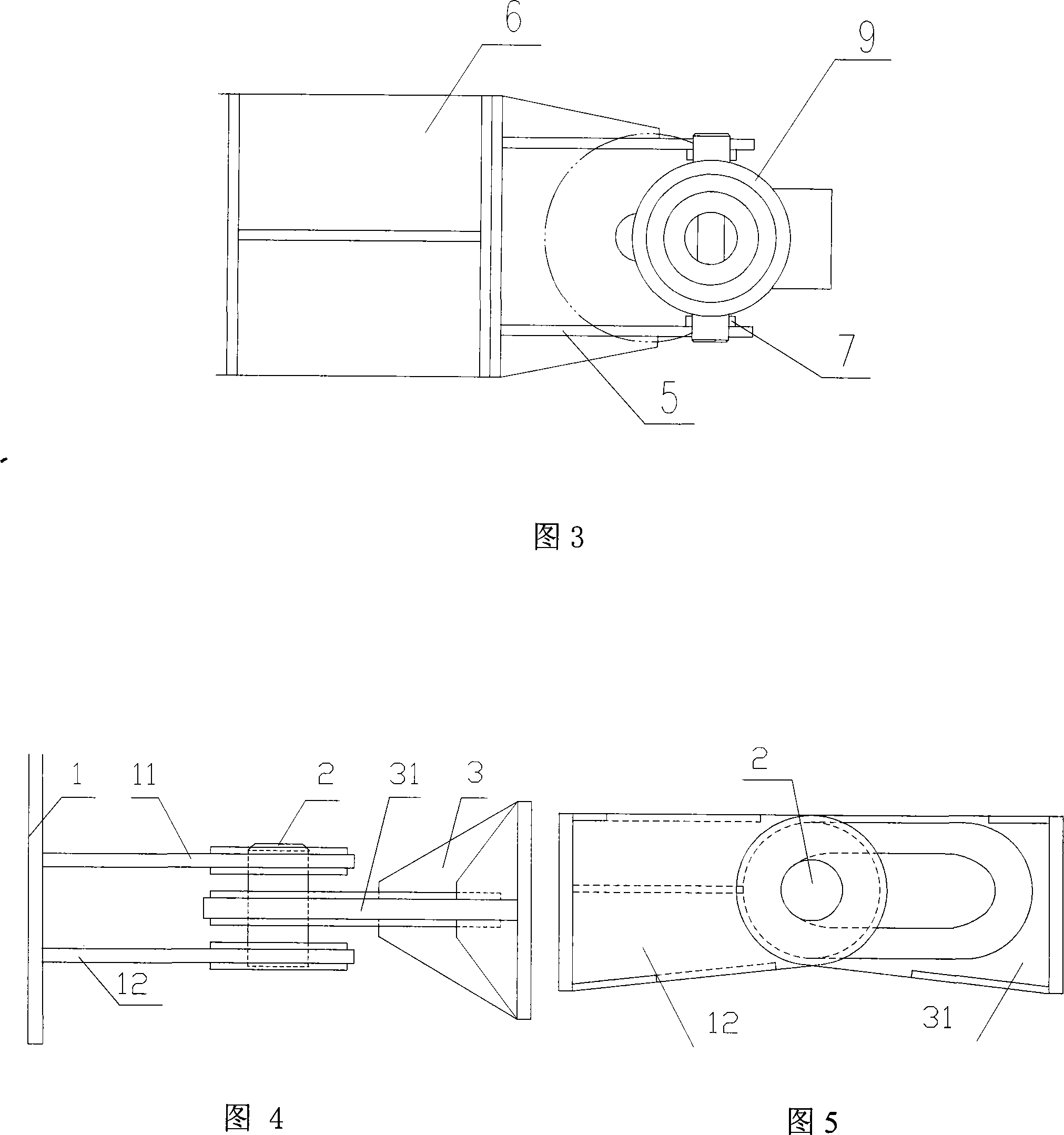
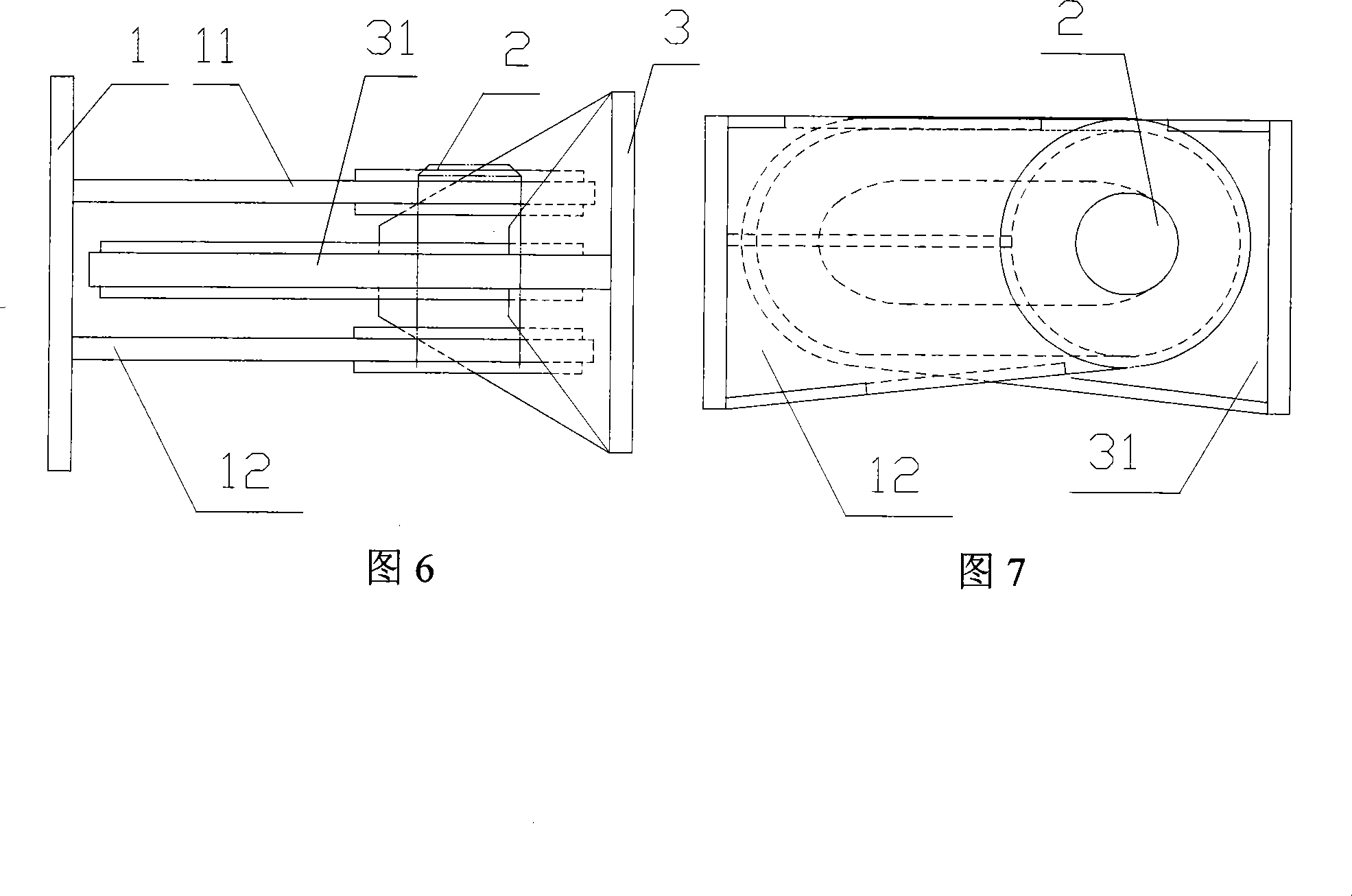
[0026] In this example, the first bolt support 1, the second bolt support 3, and the transfer support 6 are respectively fixed on the two roofs that need to be closed and connected with bolts 8. In addition to the bolt connection, welding or other connection methods. Three lug plates 11,12,13 are arranged on the first bolt support 1, and two pieces above are lock lugs 11,12, have bolt holes on it, and bolt 2 is cylindrical, thereby the bolt hole has adopted diameter than bolt 2 approximately. 5-10mm round hole, the specific size is suitable for the plug to be inserted and pulled out freely and the locking is reliable. If latch 2 is square or other shape, this hole can be changed into corresponding square or other shape. The bottom ear plate 13 is used to position the bushing 4 of the pin on the electric push rod 9. The ear plate 13 and the tw...


PUM


Abstract

The invention relates to a large allowance electronic controlling lock bolt, which is particularly applied to the lock of a retractable roof in a large stadium. The invention comprises a bolt, a first bolt support saddle, a second bolt support saddle, an electric drive pusher, a handspike support saddle, a reducing adjustment support saddle, and a bushing block; wherein, the first bolt support saddle and the second bolt support saddle are respectively fixed on two mechanisms which need locking; at least an otic placode is respectively arranged on the first bolt support saddle and the second bolt support saddle; the electric drive pusher pushes the bolt in the bushing block and ensures the bolt to be inserted into and used as the otic placode of locking ears to lock the two mechanisms. In application of the electronic controlling technology, the invention realizes the automatic lock of large roofing. A channeled slotted hole designed in the locking device allows an error band for the opposite hole site of two bolt support saddles, thereby ensuring safe and reliable insertion of the bolt; with large load bearing, the locking device can be applied to lock a large mechanism.

Description

technical field [0001] The invention belongs to the field of construction machinery, and in particular relates to a locking structure applicable to the opening and closing roof of a large stadium. Background technique [0002] The roof of the large stadium is in the shape of a hemisphere, divided into multiple pieces, and each piece of roof can slide along the track, so as to realize the opening and closing of the roof. Therefore, the track carrying the roof is correspondingly arched, and because the roof is very large and heavy, it is placed on the inclined arched track, and if no corresponding measures are taken to lock it after closing, under the action of its own weight or wind load, The roof has a tendency to slide down along the arched track and open itself, which will increase the load of the traction wire rope. Therefore, when the roof is closed, it is required to use a locking device to lock the roof safely and reliably to ensure that the roof remains closed and lo...

Claims


Application Information

Patent Timeline
Patent Type & Authority Applications(China)
IPC IPC(8): E04B7/18E04B7/08E04B1/342
Inventor 张氢李则义卞永明秦仙蓉胡晔归正邱惠清
Owner TONGJI UNIV
Why Eureka
Try Eureka