
Fin stabilizer control device with 'GPS'

A control device and fin stabilization technology, which is applied in directions such as the use of hydrofoils to reduce ship motion on the surrounding water surface, can solve problems such as loss of combat capability, influence of combat ships, dizziness of passengers and crew, and achieve good anti-rolling effect, The effect of promoting promotion and use, great economic benefits

Inactive Publication Date: 2008-08-06
704TH RES INST OF CHINA SHIPBUILDING IND CORP
View PDF0 Cites 9 Cited by
  • Summary
  • Abstract
  • Description
  • Claims
  • Application Information

AI Technical Summary

Problems solved by technology

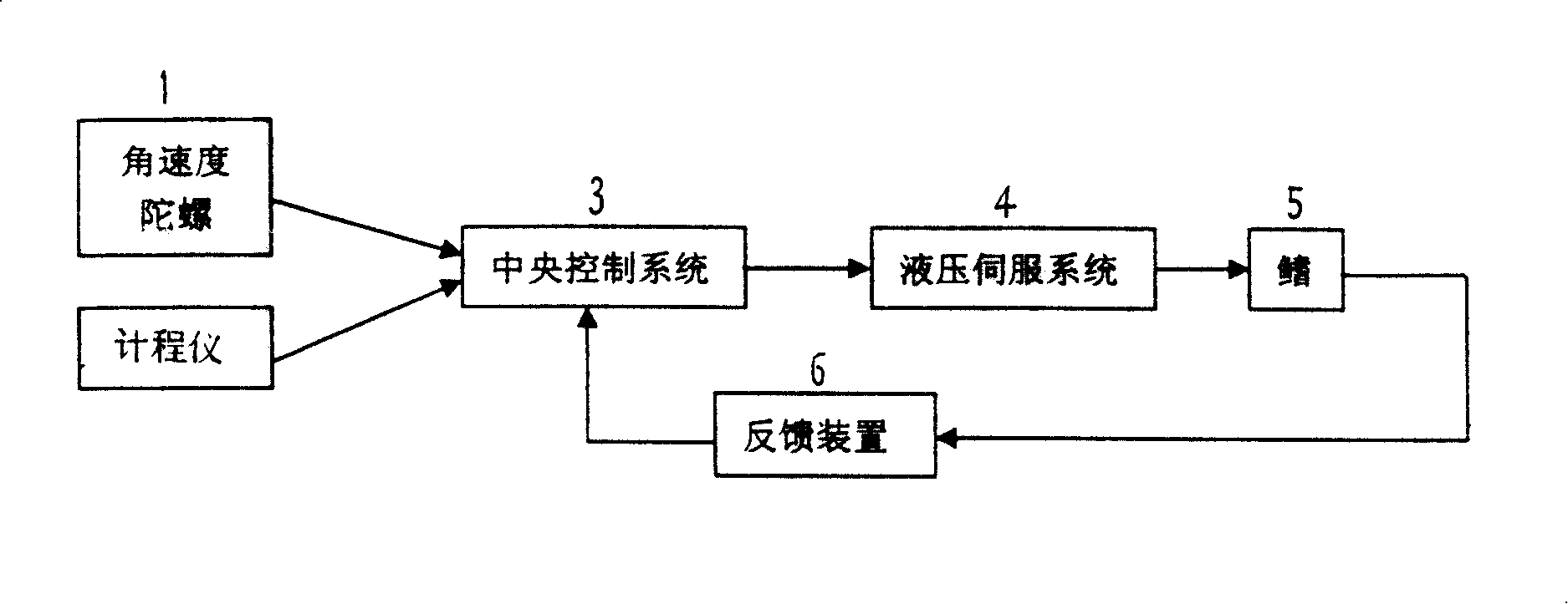
[0002] During the ocean navigation, the ship rolls under the action of wind and waves. The lateral sway of the ship will reduce its seaworthiness, damage the hull structure, affect the normal operation of equipment and instruments, and cause the cargo to shift or be damaged by collision. Passengers and crew are dizzy, severe rolling may cause danger, and it may affect or even lose combat capability for combat ships. In order to reduce the swaying of ships, operators in this technical field use various methods, such as bilge keel, anti-rolling water, etc. cabin, anti-roll gyro, anti-roll hammer and stabilizer fins and other anti-roll equipment; with the advancement of technology and the increasing number of high-speed ships, and because the effect of stabilizer fins is directly proportional to the speed of the ship, The fin stabilizer has become one of the important equipments for ships with higher speed to reduce the swing and improve the performance of the ship. The existing fin stabilizer control devices such as image 3 As shown, when the ship rolls during navigation, the gyroscope measures the ship's roll signal (including angular displacement θ, angular velocity and angular acceleration ), and then measure the ship’s sailing speed signal (ship speed v) by the log. The above-mentioned signal is input into the central control system, and after being converted and amplified, the fins are driven to rotate a corresponding angle. The stabilizing moment in the opposite direction of the rolling, the stabilizing moment will greatly damp the ship's swing, so that the rolling amplitude can be greatly reduced. Obviously, during the working process of the fin stabilizer system, the input speed signal of the log is the system The necessary condition for effective work, so the log is an indispensable element of equipment in the fin stabilizer control device. Usually, the central control system uses S7-200PLC input contacts to receive 200 pulses / nautical miles from the log. Passive or active contact signals, after identification and calculation, carry out "speed adjustment" on the fin angle of the stabilizer; Its scope of application is limited, and it cannot be mass-produced, so its production cost is extremely high, causing economic burdens to users. From the perspective of this technical field, with the increase in demand for fin stabilizers, equipment costs should be reduced, such as replacing them with low-cost equipment. The existing speed log is a measure with important economic significance; today, with the rapid development of new technologies, the Global Positioning System (GPS) has been successfully applied in a large number of sectors such as aviation, aerospace and automobiles. It is a technical potential element to replace the log, and the price is relatively low, thus providing a technical basis for the application of GPS in the fin stabilizer control device

Method used


Image

  • Fin stabilizer control device with 'GPS'
  • Fin stabilizer control device with 'GPS'
  • Fin stabilizer control device with 'GPS'

Examples


Embodiment Construction

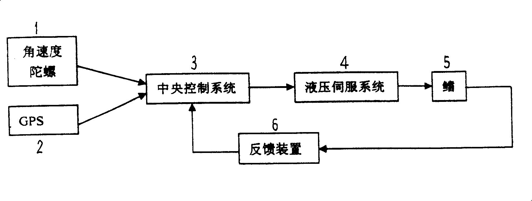
[0010] refer to figure 1 , the fin stabilizer control device with "GPS" includes angular velocity gyro 1, global positioning system (GPS) 2, central control system 3, hydraulic servo system 4, fin 5 and feedback device 6, wherein: angular velocity gyro 1, central The structures and functions of the control system 3, the hydraulic servo system 4, the fin 5 and the feedback device 6 are the same or similar to those of the existing equipment.

[0011] The angular velocity gyro 1 is the first signal source of the fin stabilizer control device with "GPS", and its output terminal is connected to the input terminal of the central control system 3. The angular velocity gyro 1 is input to the central control system 3. The angular displacement θ and angular velocity of the rolling motion and angular acceleration Signal.

[0012] "GPS" 2 is the second signal source of the fin stabilizer control device with "GPS", which can use the existing GARMIN series products. This product has a...


PUM


Abstract

The invention relates to a controlling device with a GPS fin stabilizer which mainly solves the technical problem of high cost. The adopted technical proposal is that one input end of a central system in the device which is connected with a rate gyro is taken as a first single source. Another end which is connected with a GPS used for inputting a speed signal to the central controlling system is taken as a second signal source. The two signal sources respectively send the horizontal movement signal and the speed signal of the vessel to the central controlling system and a hydraulic servo system. The signal is enlarged and the execution organization of the hydraulic servo system turns the fin for building the stable moment of the stabilizer. The angle displacement signal of the fin is input into the central controlling system through a feedback device, therefore the controlling device with a GPS fin stabilizer is suitable to a plurality of fin stabilizers.

Description

Technical field: [0001] The present invention relates to an apparatus for reducing rolling motion of a boat, and more particularly to an apparatus for reducing motion of a boat using hydrofoil action on the surrounding water. Background technique: [0002] During the ocean navigation, the ship rolls under the action of wind and waves. The lateral sway of the ship will reduce its seaworthiness, damage the hull structure, affect the normal operation of equipment and instruments, and cause the cargo to shift or be damaged by collision. Passengers and crew are dizzy, severe rolling may cause danger, and it may affect or even lose combat capability for combat ships. In order to reduce the swaying of ships, operators in this technical field use various methods, such as bilge keel, anti-rolling water, etc. cabin, anti-roll gyro, anti-roll hammer and stabilizer fins and other anti-roll equipment; with the advancement of technology and the increasing number of high-speed ships, and b...

Claims


Application Information

Patent Timeline
IPC IPC(8): B63B39/06
Inventor 尤方骏黄宇
Owner 704TH RES INST OF CHINA SHIPBUILDING IND CORP
Learn More