Twisting machine spindle brake

A technology of brakes and twisting machines, which is applied in textiles and papermaking, and can solve the problems of machine equipment damage, twisting missing strands, waste silk, etc.

A technology of brakes and twisting machines, which is applied in textiles and papermaking, and can solve the problems of machine equipment damage, twisting missing strands, waste silk, etc.

CN101235564AInactive Publication Date: 2008-08-06ι‚±η”«ζž—

Image

  • Twisting machine spindle brake
  • Twisting machine spindle brake

Examples


Embodiment Construction

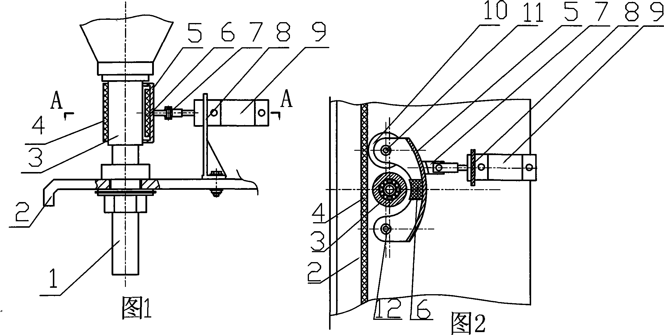
[0012] In the spindle brake of the twisting machine shown in Figure 1 and Figure 2, the spindle includes a spindle base 1 and a spindle disc 3, the spindle base 1 is fixed on the dragon bar 2, and the spindle disc 3 can be rotated at a high speed through the spindle rod. On the spindle base 1; the transmission dragon belt 4 is tangentially attached to the spindle disc 3 to drive the spindle for high-speed twisting, winding and rotation. On the opposite side of the ingot 3 and the drive belt 4, there is a brake swing arm 5, the brake swing arm 5 adopts a steel plate stamping part; On the dragon rib 2, the other end of the brake swing arm 5 is equipped with a dragon belt push wheel 10 through the dragon belt push wheel pin 11 and a rolling bearing (not shown in the figure), and the dragon belt push wheel 10 is close to the transmission dragon belt 4 the drive side.

[0013] A brake block 6 is fixedly mounted on the inner side of the brake swing arm 5, and the brake block 6 is m...


PUM


Abstract

The invention discloses a twisting frame spindle brake, which comprises a spindle brake block, wherein the spindle brake block is fixedly mounted on a brake rocking arm, one end of the brake rocking arm is hingedly supported, the other end of the brake rocking arm is provided with a rotatable tangential belt push tug, the brake rocking arm is further provided with a brake cylinder, the brake rocking arm is hingedly supported on the rail through a brake rocking arm hinged fulcrum, the brake cylinder is supported on the rail through a cylinder support, the brake cylinder is movably connected with the brake rocking arm through a brake rocking arm connecting piece. The twisting frame spindle brake has the advantages that the structure is simple, the brake is reliable and accurate, the automatic brake of a spinning device can be realized, and the brake is beneficial to improve the automatic degree of devices, which is widely applied to spinning devices such as twisting frames, doubling frames, compound twisting frames and spinning machines and the like.

Description

technical field [0001] The invention relates to a textile machine, in particular to a twisting machine and a parallel-twisting compound twisting machine, in particular to a spindle braking device of a twisting machine or a parallel-twisting compound twisting machine. Background technique [0002] Twisting machine or compound twisting machine is a textile machine that twists monofilament (yarn) through monofilament (yarn), merges and plies and twists into strands. The stress distribution of inner and outer fibers of single yarn after twisting is obvious Improvement, thereby greatly improving the overall performance of the yarn such as strength, evenness, abrasion resistance and appearance. [0003] Spindle is an indispensable and important part for twisting and winding of single yarn or ply in twisting machine or compound twisting machine. Because the spindle is always in the process of twisting and winding, there is always the phenomenon of yarn breakage, if the monofilamen...

Claims


Application Information

Patent Timeline
06 Aug 2008
Publication
CN101235564A
IPC
D01H7/22
Inventors
ε’ε›½η”Ÿ; ι‚±η”«ζž—