Electrooptical distance measuring device

A photoelectric rangefinder and rangefinder technology, which is applied in the direction of radio wave measurement systems, instruments, and measurement devices, can solve the problems of complex manufacturing, photodiodes cannot be firmly mechanically fixed to the circuit board, etc., and achieve good measurement performance Effect

Inactive Publication Date: 2008-08-06
LEICA GEOSYSTEMS AG
View PDF2 Cites 11 Cited by
  • Summary
  • Abstract
  • Description
  • Claims
  • Application Information

AI Technical Summary

Problems solved by technology

This fixed step to be carried out in the gauge, which necessarily moves individual electronic components, complicates manufacturing
In particular, the photodiode may not have been mechanically fastened securely to the board

Method used


Image

  • Electrooptical distance measuring device
  • Electrooptical distance measuring device
  • Electrooptical distance measuring device

Examples


Embodiment Construction

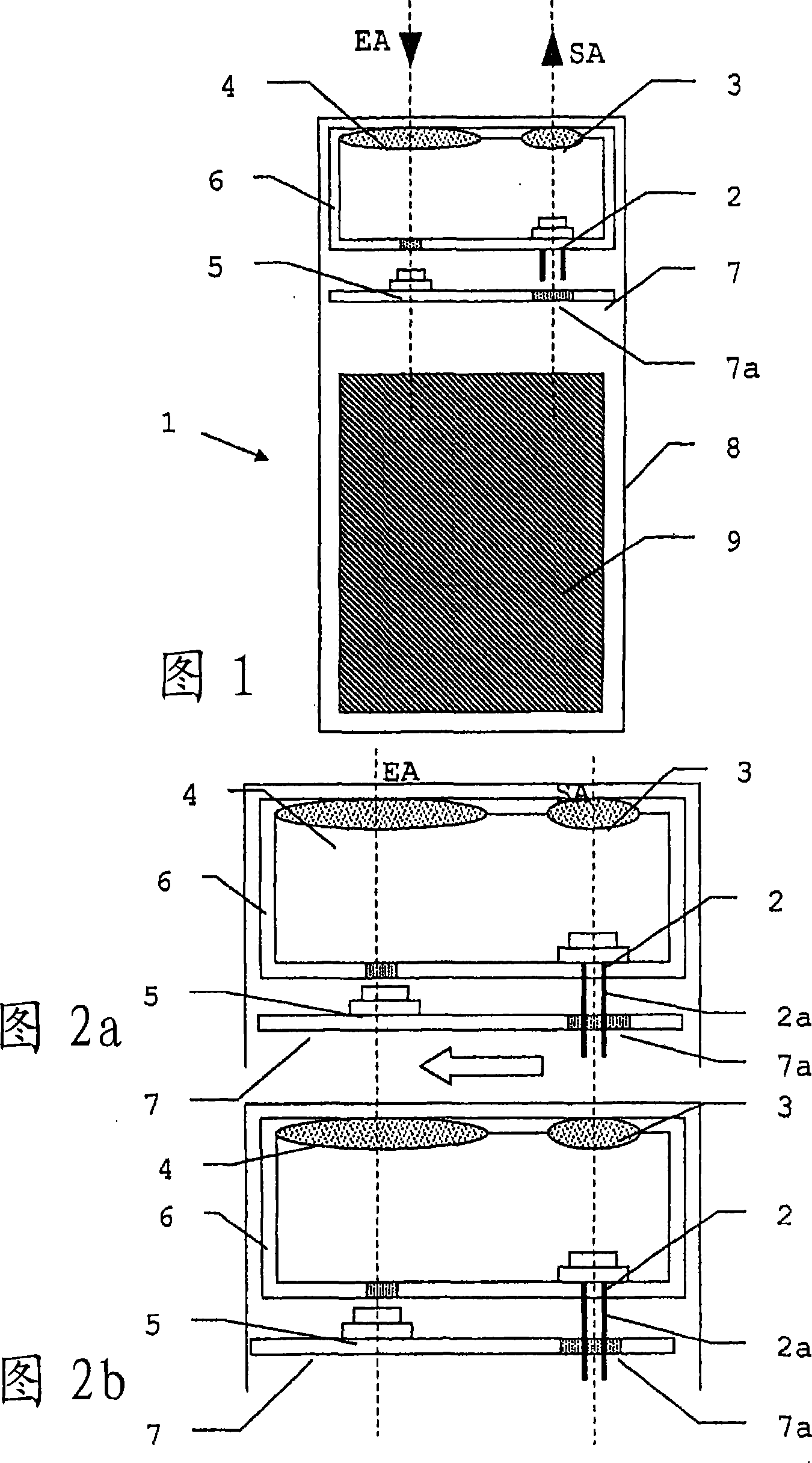
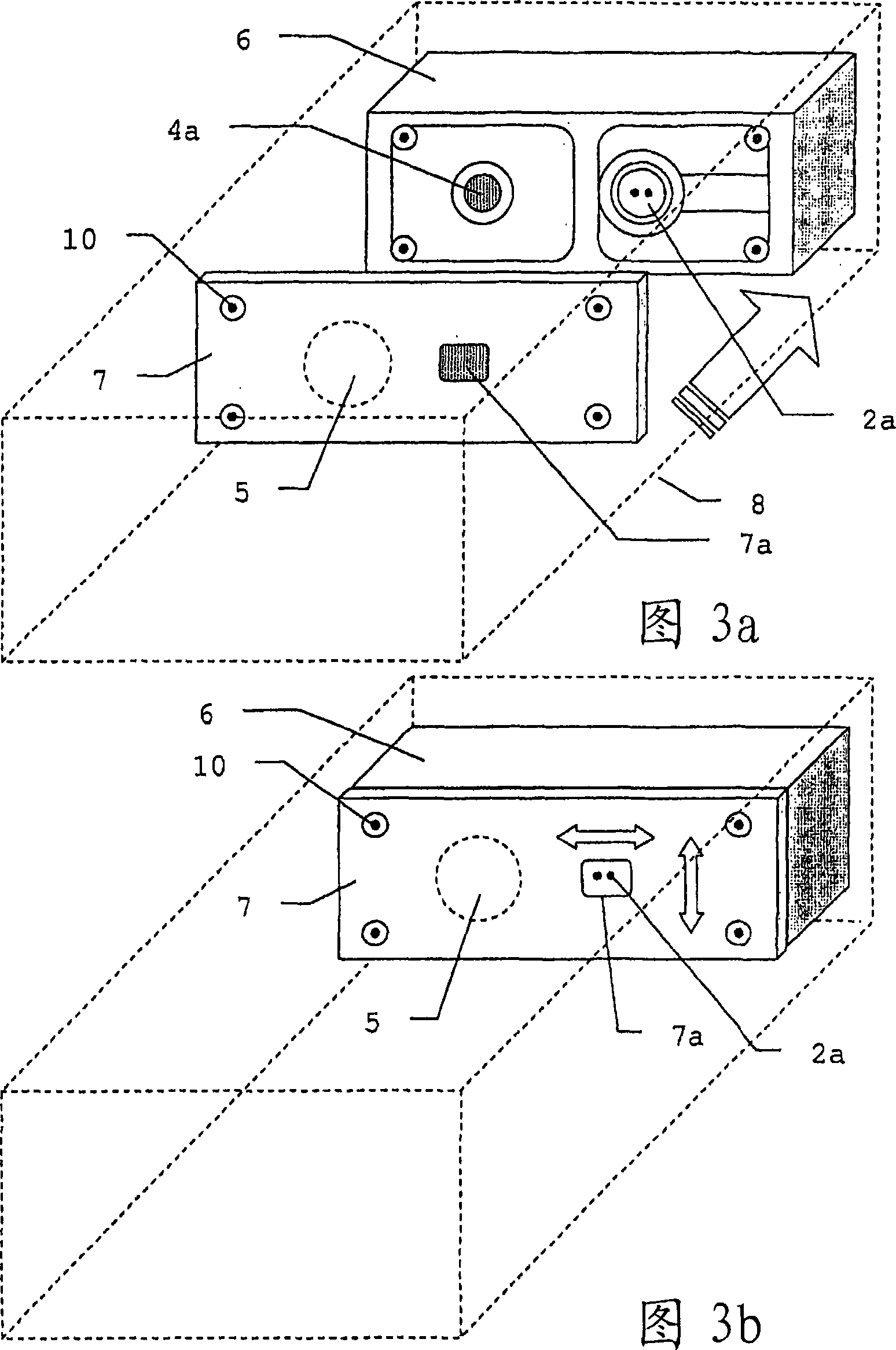
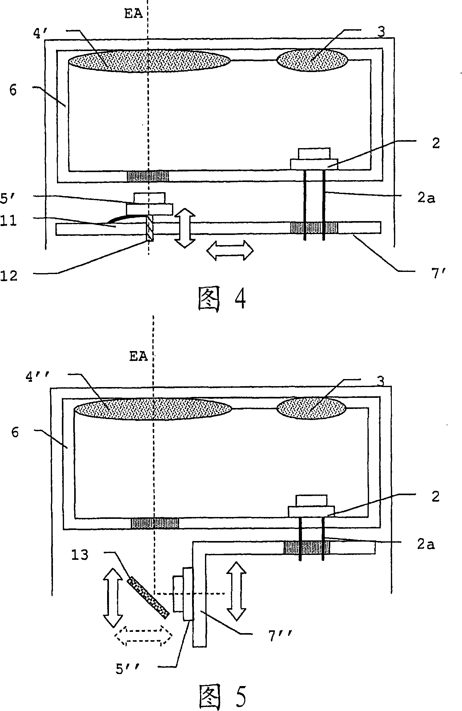
[0031] Fig. 1 represents the first embodiment according to the photoelectric range finder 1 of the present invention, and it has the laser diode 2 as transmitter, and it sends light beam or light to irradiate the target to be measured by emitting mirror group 3, and emitting mirror group 3 has emitting Axis SA. The light reflected by the object to be measured is received by the receiving mirror group 4 with the receiving axis EA and directed to the measuring receiver 5 such as an avalanche photodiode. In addition, the emission axis SA and the reception axis EA are oriented parallel or slightly inclined relative to each other, so the arrangement structure in the measurement area has the characteristic that the optical paths are parallel to each other and staggered. Furthermore, the transmitting optics group 3 and the receiving optics group 4 can advantageously be mounted on a common optics mount 6 , which also accommodates the laser diode 2 and securely fixes it relative to the...


PUM


Abstract

The invention provides a photoelectric distance measuring instrument, which has a transmitter for emitting light to illuminate the target to be measured, a transmitting mirror group and a receiving mirror group that are firmly fixed relative to the transmitter; in the photoelectric distance measuring instrument, there is The measuring receiver (5) and the carrier of the receiving circuit are positioned relative to the receiver mirror group, wherein the measuring receiver (5) is fitted on the carrier (7) in a firmly connected manner in at least two directions of movement.

Description

technical field [0001] The invention relates to an optoelectronic distance meter according to the preamble of claim 1 and a method of calibrating such an optoelectronic distance meter according to the preamble of claim 14 . Background technique [0002] Distance finders in the form of hand-held measuring devices or industrial sensors have long been known and are commercially available, with distance measuring ranges of up to 200 meters and which are used, for example, for building surveys, for example for spatial three-dimensional measurements . For this purpose, the transmitter emits intensity-modulated light, mostly at wavelengths in the visible range, which simplifies the aiming of the measuring point. The rays are reflected or scattered by the target to be measured and received by the receiver. According to the phase of the modulated light relative to the emitter, the distance to the target to be measured is obtained. [0003] Such a measuring device is known, for exa...

Claims


Application Information

Patent Timeline
Patent Type & Authority Applications(China)
IPC IPC(8): G01S7/497G01S7/481
CPCG01S7/481G01S7/4972G01S17/36
Inventor 弗朗茨·施普伦格
Owner LEICA GEOSYSTEMS AG
Why Eureka
Try Eureka