Fast heating device
A heat device and heat source technology, applied in water heaters, heat storage heaters, fluid heaters, etc., to achieve the effect of reducing noise
- Summary
- Abstract
- Description
- Claims
- Application Information
AI Technical Summary
Problems solved by technology
Method used
Image
Examples
no. 1 example
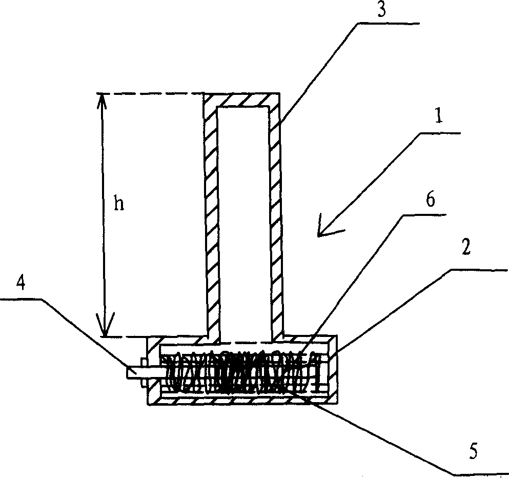
[0024] figure 1 It is a schematic structural diagram of the first embodiment of the fast heating device of the present invention.
[0025] like figure 1 As shown, the present invention provides a fast heating device 1, comprising: a liquid medium working medium accommodating part 2 for accommodating a liquid working medium 5; a heat transfer part 3, which is mutually connected with the liquid working medium accommodating part 2 Connected and sealed and evacuated, the ratio between the volume of the heat transfer part 3 and the volume of the liquid working medium accommodating part 2 and the volume of the liquid medium is in the range of 85:1 to 11:1; For heating the liquid working medium 5; the metal wool 6 is arranged in the liquid working medium accommodating part 2, the shape of the metal wool 6 is adapted to the shape of the inner wall of the liquid working medium accommodating part 2, the metal wool 6 is used to reduce the noise generated when the liquid working medium ...
no. 2 example
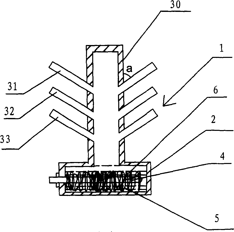
[0036] figure 2 It is a schematic structural diagram of the second embodiment of the fast heating device of the present invention.
[0037] like figure 2 As shown, the second embodiment of the present invention is different from the first embodiment in that the heat transfer part 3 includes a main body 30 and a plurality of heat dissipation branch pipes 31 , 32 and 33 provided on the main body 30 . The heat dissipation branch pipes 31 , 32 and 33 help to dissipate the heat transferred by the heat transfer part 3 to the outside more quickly.
[0038] There is an included angle a between the heat dissipation branch pipes 31 , 32 and 33 and the heat transfer part 3 , and the included angle a may be an acute angle, for example, 20° to 60°. Different shapes of radiating fins can also be connected to each radiating branch pipe.
no. 3 example
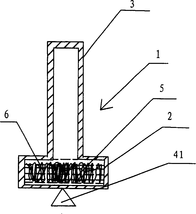
[0040] image 3 It is a schematic structural diagram of the third embodiment of the fast heating device of the present invention.
[0041] like image 3 As shown, the difference between the third embodiment of the present invention and the first embodiment is that the electric heating pipe 4 in the first embodiment is replaced by a combustion heat source 41 located outside the liquid working medium accommodating portion 2 .
[0042]In the third embodiment, the shape of the metal fleece 6 is adapted to the shape of the inner wall of the liquid working medium accommodating portion 2, so that the metal fleece 6 can fully contact the heated inner wall of the liquid working medium accommodating portion 2, so that the liquid The large bubbles generated when the working medium 5 changes from liquid to gas are divided into several small bubbles, which reduces the noise generated when the bubbles burst, thereby reducing the noise.
[0043] The metal fleece 6 can have a predetermined ...
PUM
 Abstract
Description
Claims
Application Information
 - R&D
- Intellectual Property
- Life Sciences
- Materials
- Tech Scout
- Unparalleled Data Quality
- Higher Quality Content
- 60% Fewer Hallucinations
Browse by: Latest US Patents, China's latest patents, Technical Efficacy Thesaurus, Application Domain, Technology Topic, Popular Technical Reports.
© 2025 PatSnap. All rights reserved.Legal|Privacy policy|Modern Slavery Act Transparency Statement|Sitemap|About US| Contact US: help@patsnap.com


