Lens module assembled apparatus and method

A technology for lens modules and assembly equipment, applied in installation, optics, instruments, etc., can solve the problems of time-consuming positioning, lower assembly yield, and inaccuracy, and achieve the effect of accurate and efficient assembly

A technology for lens modules and assembly equipment, applied in installation, optics, instruments, etc., can solve the problems of time-consuming positioning, lower assembly yield, and inaccuracy, and achieve the effect of accurate and efficient assembly

CN101241218AInactive Publication Date: 2008-08-13HONG FU JIN PRECISION IND (SHENZHEN) CO LTD +1

Image

  • Lens module assembled apparatus and method
  • Lens module assembled apparatus and method

Examples


Embodiment Construction

[0010] The present invention will be described in further detail below in conjunction with the accompanying drawings.

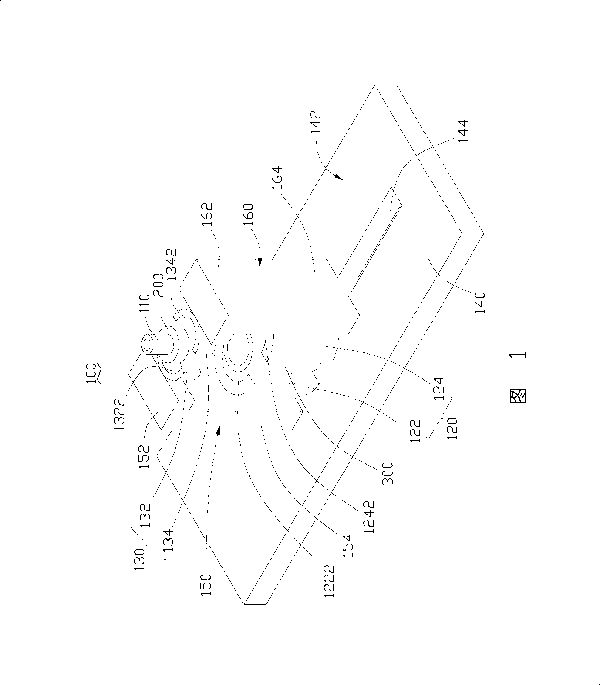
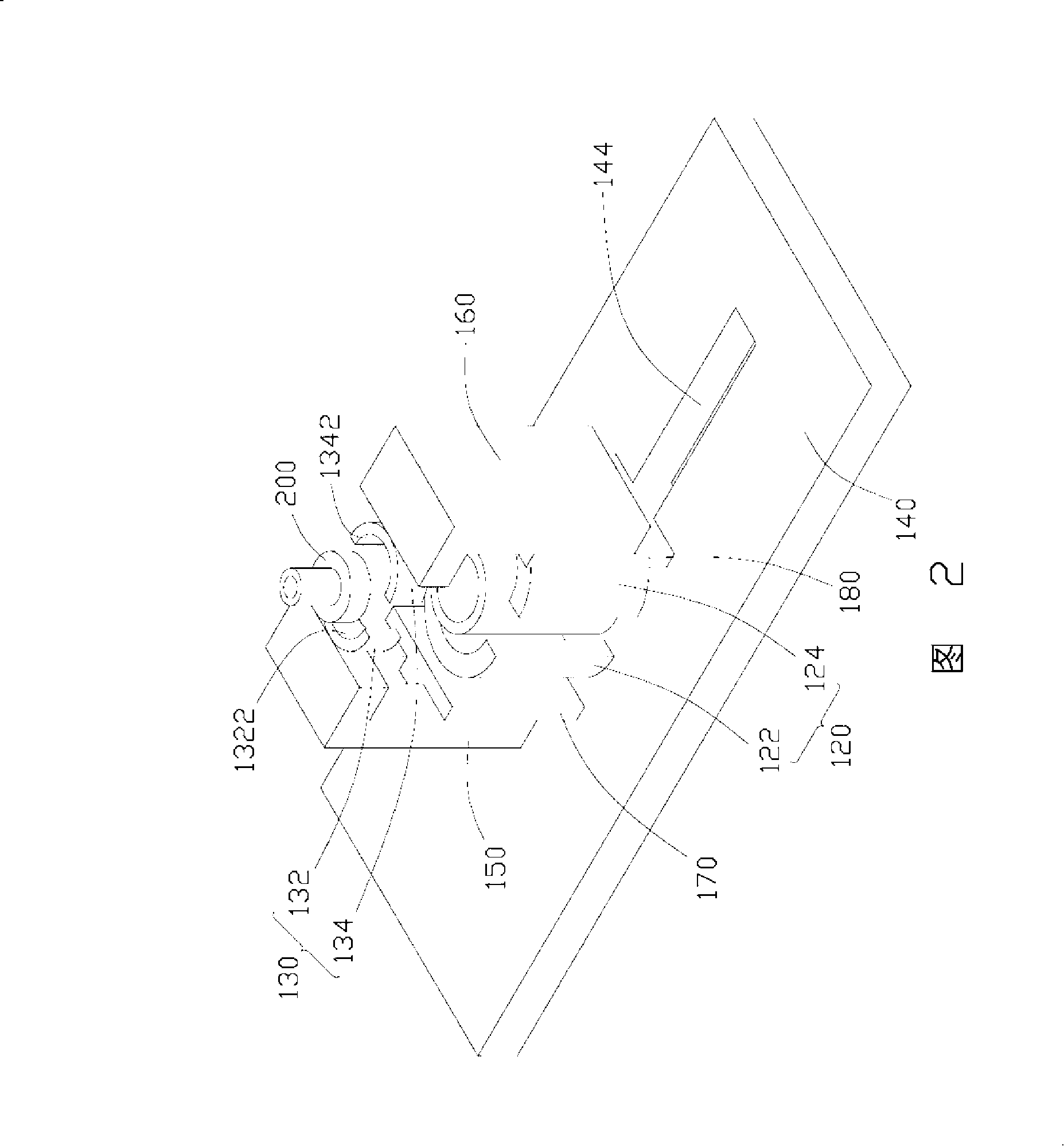
[0011] Please refer to FIG. 1 , a lens module assembling device 100 provided by an embodiment of the present invention includes a pick-up device 110 , a holder 120 and a guide 130 .

[0012] The pick-up device 110 is used to take out the optical components 200 such as lenses and infrared filters from the tray (not shown) carrying the optical components 200 , and assemble the taken-out optical components 200 into the lens barrel 300 . In this embodiment, the pick-up device 110 is a vacuum suction nozzle, which can be connected with an air cylinder (not shown) to absorb the optical element 200 . Of course, it can be understood that the pick-up device 110 may also be other devices capable of taking and placing the optical element 200, such as a robot arm.

[0013] The holding member 120 is used to hold the lens barrel 300 , and includes a first holding portion ...


PUM


Abstract

The invention provides a lens module assembling device, comprising a fetching device for fetching optical elements to be assembled, a holding unit for holding a cylinder, and a guide unit for guiding correction of the optical elements. The central axis of the holding unit and that of the guiding unit are coinciding. The invention also provides a method for assembling a lens module by using the lens module assembling device. The lens module is assembled with high precision and high efficiency by assembling the optical elements into the cylinder after guiding correction is performed.

Description

technical field [0001] The invention relates to a lens module assembly device, in particular to a lens module assembly device and an assembly method capable of accurately assembling a lens module. Background technique [0002] With the development of camera technology, lens modules are widely used in camera devices for various purposes, and the combination of lens modules with various portable electronic devices, such as mobile phones, is favored by many consumers. [0003] A lens module generally includes a lens barrel, a lens assembled in the lens barrel, an infrared cut filter, and a spacer for separating the above-mentioned components. When assembling the lens module, the lens barrel is usually fixed on a machine first, and then optical elements such as lenses and infrared cut filters are assembled into the lens barrel by using a pick-up device, such as a suction nozzle. However, during the assembly process, the axes of optical elements such as lenses and infrared cut f...

Claims


Application Information

Patent Timeline
13 Aug 2008
Publication
CN101241218A
IPC
G02B7/02; G02B7/04; G03B30/00
Inventors
吴承勋