Ice and snow fusion method for air power transmission line
A power transmission line, ice and snow technology, applied to electrical components, circuit devices, overhead installations, etc., can solve problems such as low efficiency, impracticality, and inability to use load current heat
Inactive Publication Date: 2010-12-01
傅雅芬
View PDF0 Cites 0 Cited by
- Summary
- Abstract
- Description
- Claims
- Application Information
AI Technical Summary
Problems solved by technology
However, this kind of vehicle must generate a lot of electric energy, which is expensive and inefficient. It is powerless for long-distance snow accumulation on wires, so it is not practical. Some people also advocate adding a line for heating and deicing on the high-voltage line. Alternate power transmission, but in this way, the heat generated by the original transmission line cannot be used, and the second is to add a line
In short, these are the full-time step-down short-circuit method, so the heat generated by the original load current cannot be used, and the work can only be done when the power is off.
Method used
View moreImage
Smart ImageViewing Examples
Examples
Embodiment Construction
Login to View More PUM
 Abstract
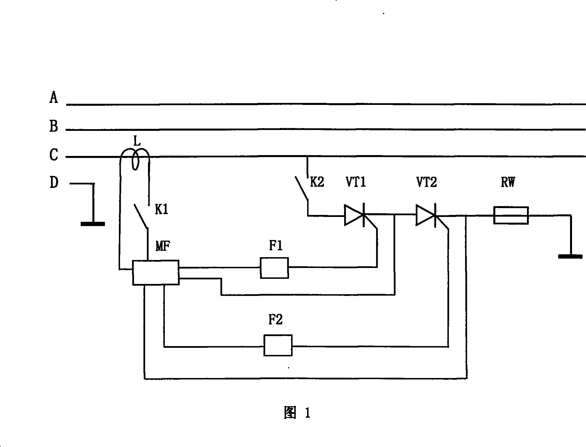
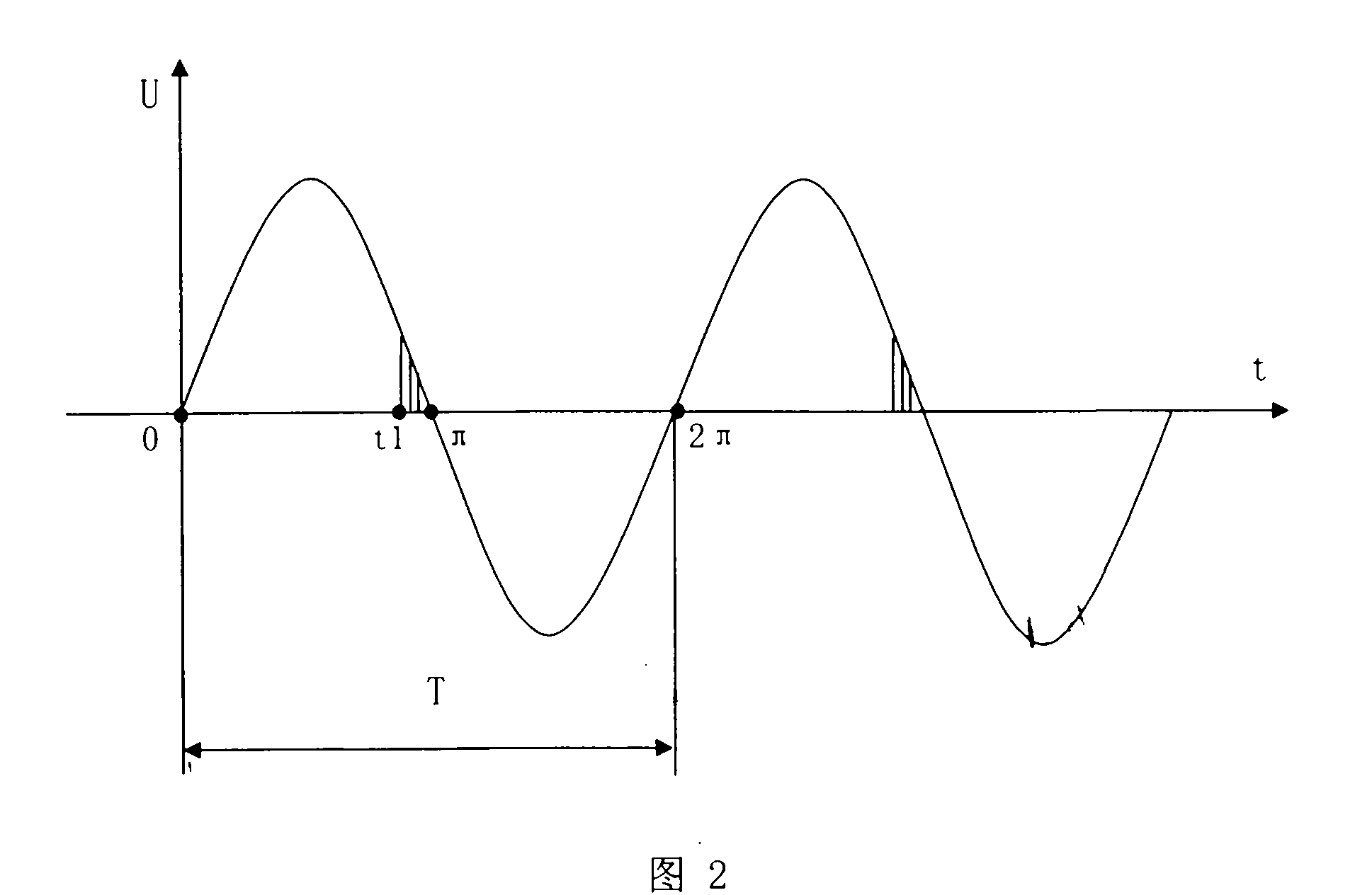
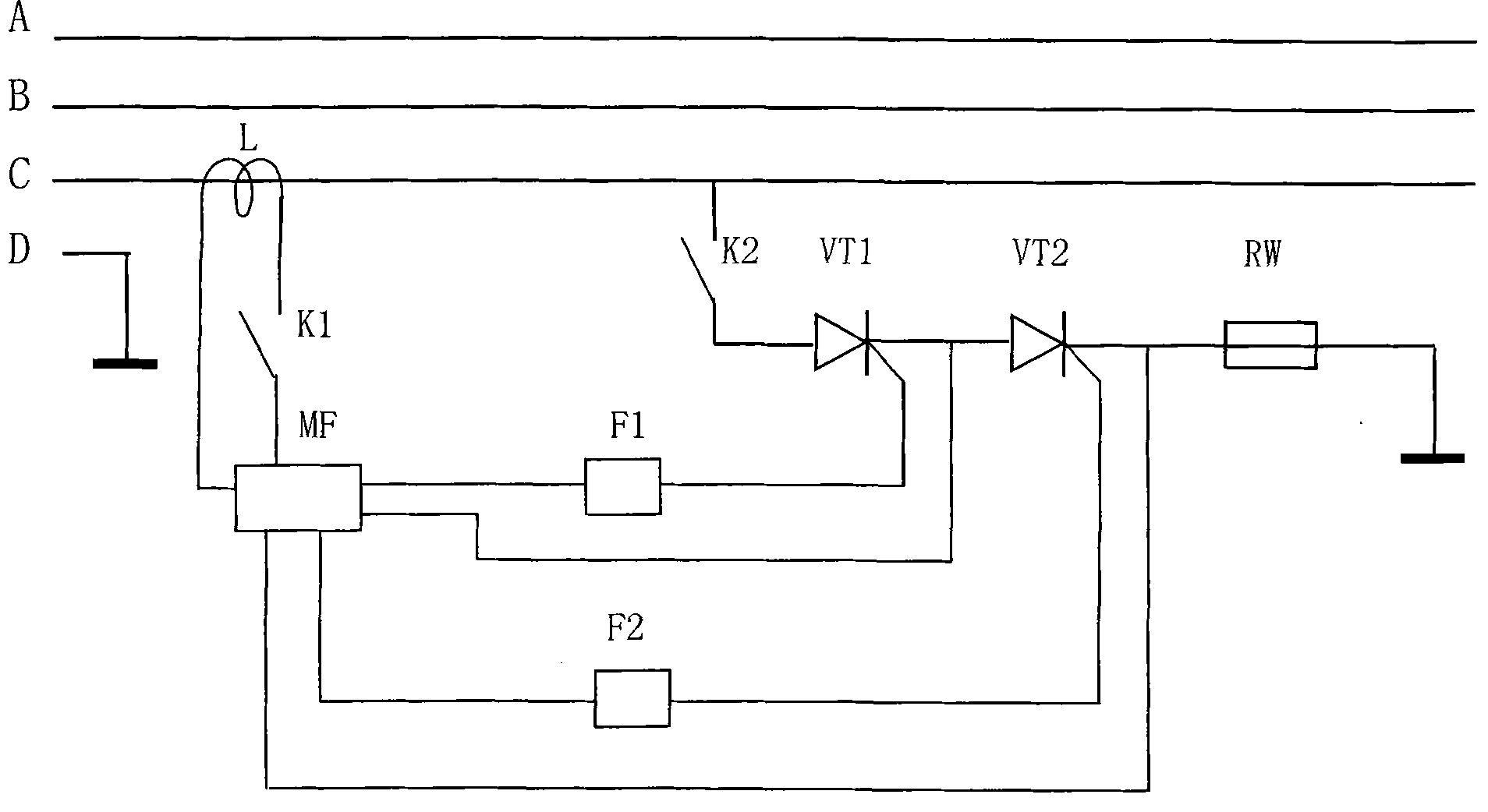
The present invention provides a method for melting the ice on the overhead electric transmission line, under the original load of the three-phase electric transmission line by connecting the major loop of the thyristor between each phase line of the circuit with ice and the earth standing for the zero potential through an electric brake, the phases are respectively obtained from three phase lines, the phase signals are accessed into the respective pulse generator to generate lower-edge positive pulse by each generator, the positive pulse is used for triggering the control pole of thyristor in a same phase line to lead to the earth-conducting of the thyristor in order to increase the heat generating quantity of the conducting wire, the pulse generator is also provided with a pulse triggering time regulator with which the conducting time of the thyristor is controlled to lead to that the heat generating quantity of the electric transmission line confirms to the requirement for melting the ice thereby realizing the purpose that the power is not off when the ice is melted on the overhead electric transmission line.
Description
Method for Melting Ice and Snow of Elevated Transmission Line technical field A method for melting ice and snow on electric wires, in particular to a method for melting ice and snow on overhead transmission lines. Background technique To transmit power to users from a distance, the wires must be placed on elevated insulated towers, but when it snows in winter, snowflakes fall on the wires and freeze, forming ice and snow lines, and the ice and snow accumulate thicker and thicker, making the wires The weight increased greatly, causing accidents such as short circuit, breakage of wires, and the toppling of the column towers on which the wires were erected. For example, the ice and snow lines formed by the heavy snow in early 2008 caused huge losses to the southern region. However, the current deicing method mainly relies on artificial deicing. In Canada, there is also a kind of electric deicing vehicle, which drives the car under the frozen wire, connects the low-voltage cur...
Claims
Login to View More Application Information
Patent Timeline
 Patent Type & Authority Patents(China)
IPC IPC(8): H02J3/00H02G7/16
Inventor 陈宜中傅雅芬
Owner 傅雅芬
Features
- R&D
- Intellectual Property
- Life Sciences
- Materials
- Tech Scout
- Unparalleled Data Quality
- Higher Quality Content
- 60% Fewer Hallucinations
Learn More Browse by: Latest US Patents, China's latest patents, Technical Efficacy Thesaurus, Application Domain, Technology Topic, Popular Technical Reports.
© 2025 PatSnap. All rights reserved.Legal|Privacy policy|Modern Slavery Act Transparency Statement|Sitemap|About US| Contact US: help@patsnap.com


