
Variable gain amplifying circuit

一种增益放大电路、可变的技术,应用在放大器、增益控制、放大的控制等方向,能够解决增益范围有限等问题,达到宽增益范围的效果

Inactive Publication Date: 2008-08-13
MEDIATEK SINGAPORE PTE LTD SINGAPORE
View PDF0 Cites 17 Cited by
  • Summary
  • Abstract
  • Description
  • Claims
  • Application Information

AI Technical Summary

Problems solved by technology

This results in a very limited gain range for each gain stage

Method used


Image

  • Variable gain amplifying circuit
  • Variable gain amplifying circuit
  • Variable gain amplifying circuit

Examples


Embodiment Construction

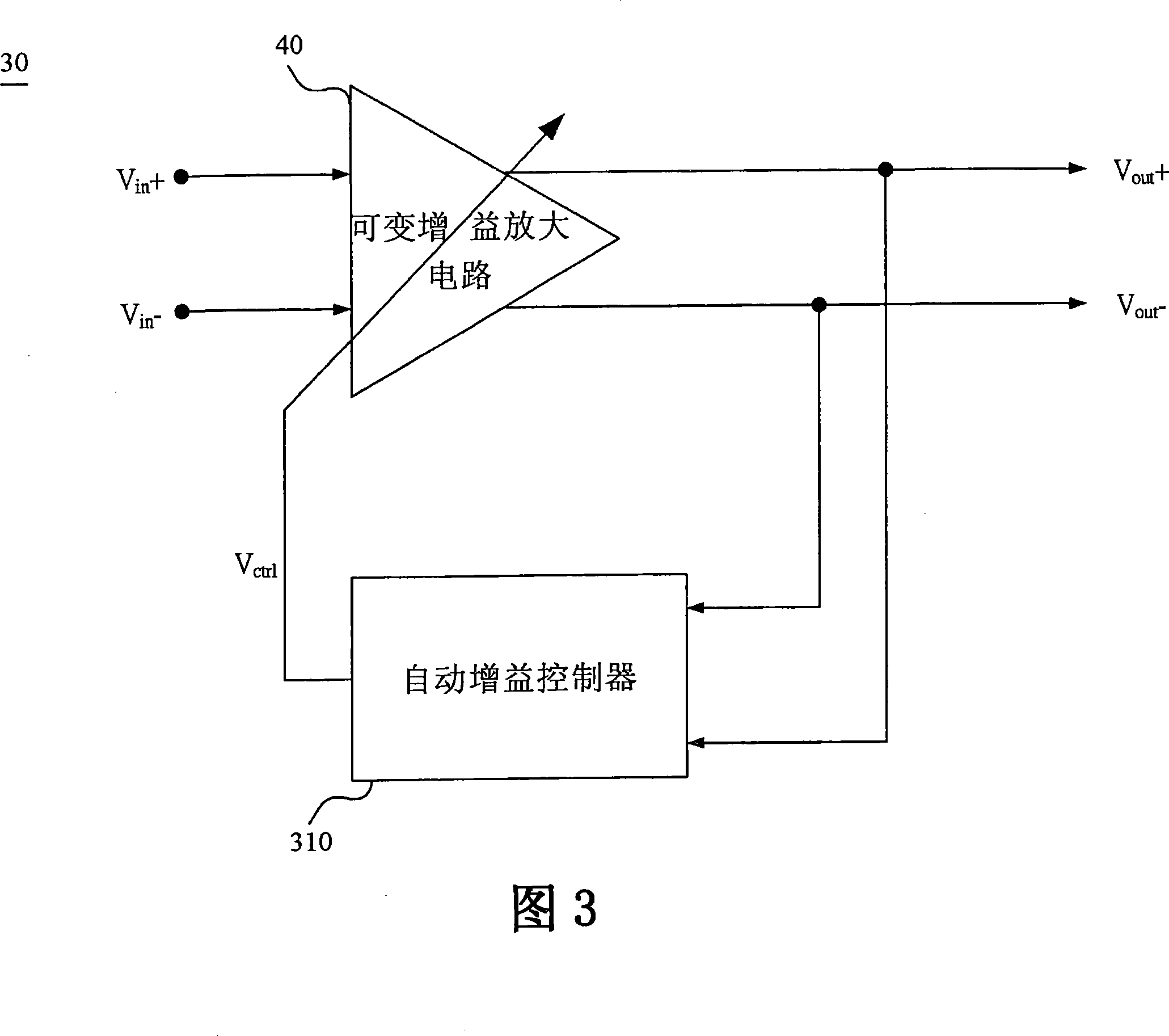
[0023] FIG. 3 is a block diagram of an automatic gain control system 30 according to an embodiment of the present invention. The automatic gain control system 30 includes an automatic gain controller (Automatic Gain Controller, AGC) 310 and a variable gain amplification (Variable Gain Amplifying, VGA) circuit 40 . Automatic gain controller 310 generates a control voltage V ctrl to control the gain of the variable gain amplifying circuit 40 . The variable gain amplifying circuit 40 receives a pair of differential pair input signals V in+ and V in- , to amplify the control voltage corresponding to V ctrl The variable gain, then the variable gain amplifier circuit 40 outputs the differential pair amplified signal V out+ and V out- .

[0024] FIG. 4 is a circuit diagram of a variable gain amplifier circuit 40 according to an embodiment of the present invention. The variable gain amplifier circuit 40 of this embodiment includes a first gain stage 401 , a second gain stage 40...


PUM


Abstract

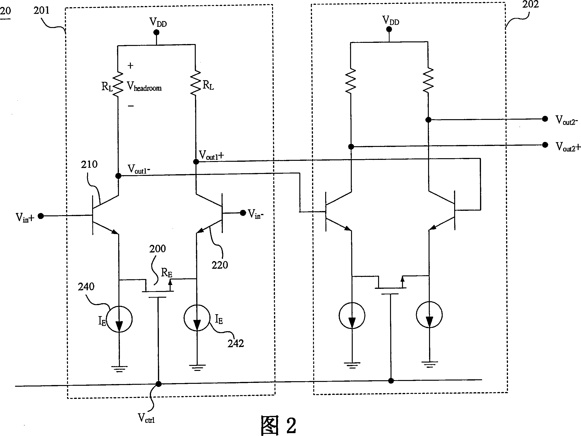
A variable gain amplifying circuit comprises two stages, a first stage and a second stage with a common voltage-to-current converter. Each stage comprises two BJTs, two voltage controlled current sources, a variable resistor with a variable resistance, and the common voltage-to-current converter. The two BJTs construct a differential amplifier for amplifying a pair of differential signals. The variable resistor with the variable resistance is connected between the emitters of the two BJTs wherein the variable resistance of the variable resistor is represented as RE. The variable resistance RE is controlled by a control voltage Vctrl. The two voltage controlled current sources are respectively connected between the corresponding emitter of BJTs and ground. The currents respectively through the voltage controlled current sources are equal to each other and represented as IE. The current IE is controlled by the common voltage-to-current converter according the control voltage Vctrl. For the same change of control voltage, each stage of the variable gain amplifying circuit can provides wider amplifying range, so that wider total amplifying range can be realized by using less stages.

Description

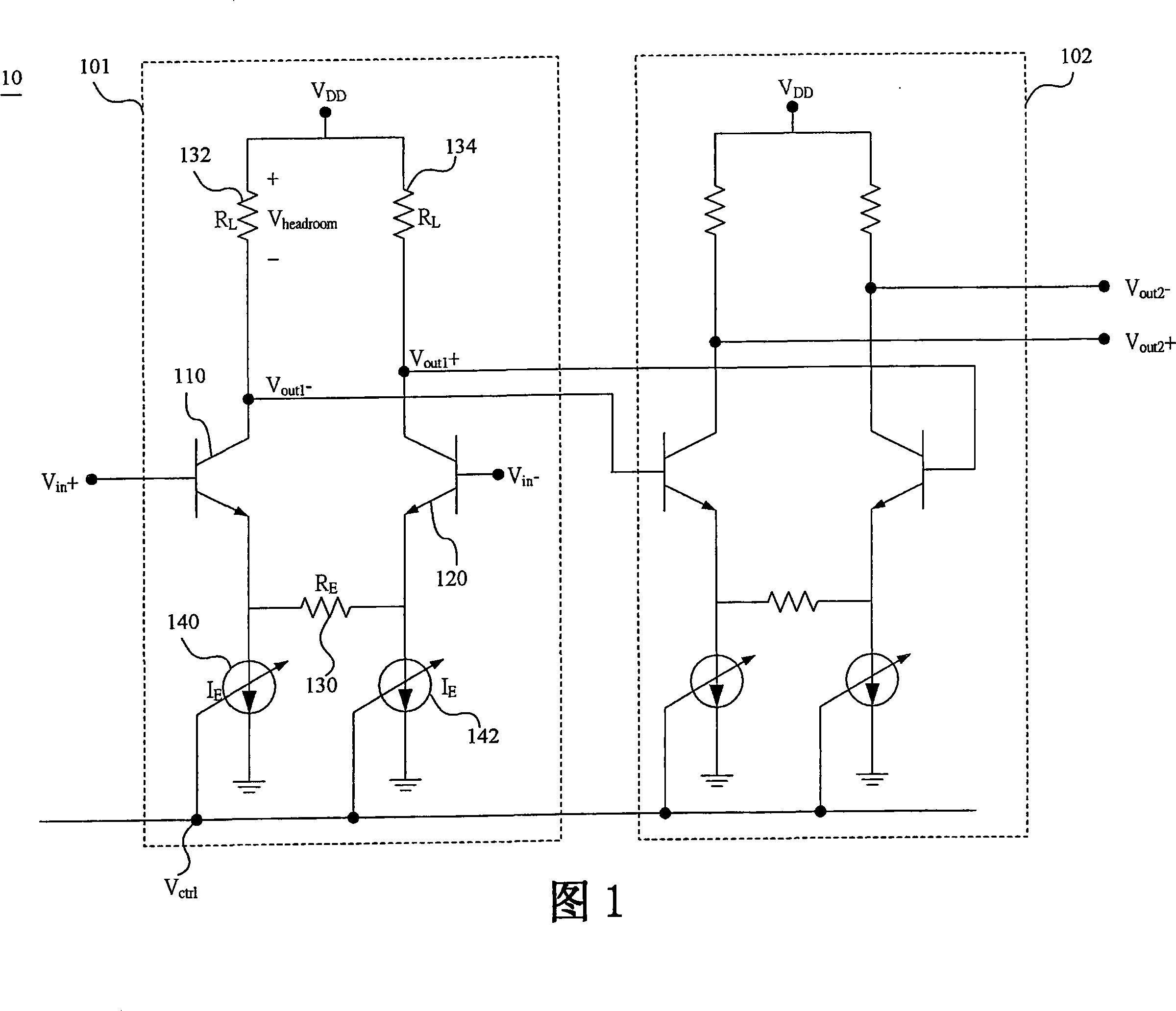
technical field [0001] The invention relates to a variable gain amplifying circuit, in particular to a variable gain amplifying circuit with wide gain range and fast adjustment. Background technique [0002] Automatic gain control (Automatic gain control, AGC) systems are commonly used in various electronic products, such as communication products, memory storage products, wireless transceivers, and the like. The automatic gain control system includes a variable gain amplifier for amplifying a received signal. The amplitude of the received signal can vary within a wide range, so that the amplified signal output by the variable gain amplifier can have a substantially constant amplitude. [0003] FIG. 1 is a circuit diagram of a conventional variable gain amplifier circuit 10 . The variable gain amplifier circuit 10 is used to amplify the differential input signal V in+ and V in- . The variable gain amplifier circuit 10 includes a plurality of gain stages, such as a first ...

Claims


Application Information

Patent Timeline
Patent Type & Authority Applications(China)
IPC IPC(8): H03G3/30H03F3/45
CPCH03G1/0029H03F3/45197H03F2203/45466H03F2203/45492H03F2203/45652H03F2203/45244H03F2203/45494
Inventor 连伟量瑞温德·德哈玛林根黄天文
Owner MEDIATEK SINGAPORE PTE LTD SINGAPORE
Learn More