Hydraulic water, oil squeezing apparatus

A hydraulic and capping technology, used in metal processing equipment, metal rolling, manufacturing tools, etc., can solve the problem of low strip quality

Inactive Publication Date: 2008-08-20
朱惠兴
View PDF0 Cites 0 Cited by
  • Summary
  • Abstract
  • Description
  • Claims
  • Application Information

AI Technical Summary

Problems solved by technology

At present, there is no supporting device for removing the cooling liquid atta...

Method used


Image

  • Hydraulic water, oil squeezing apparatus

Examples


Embodiment Construction

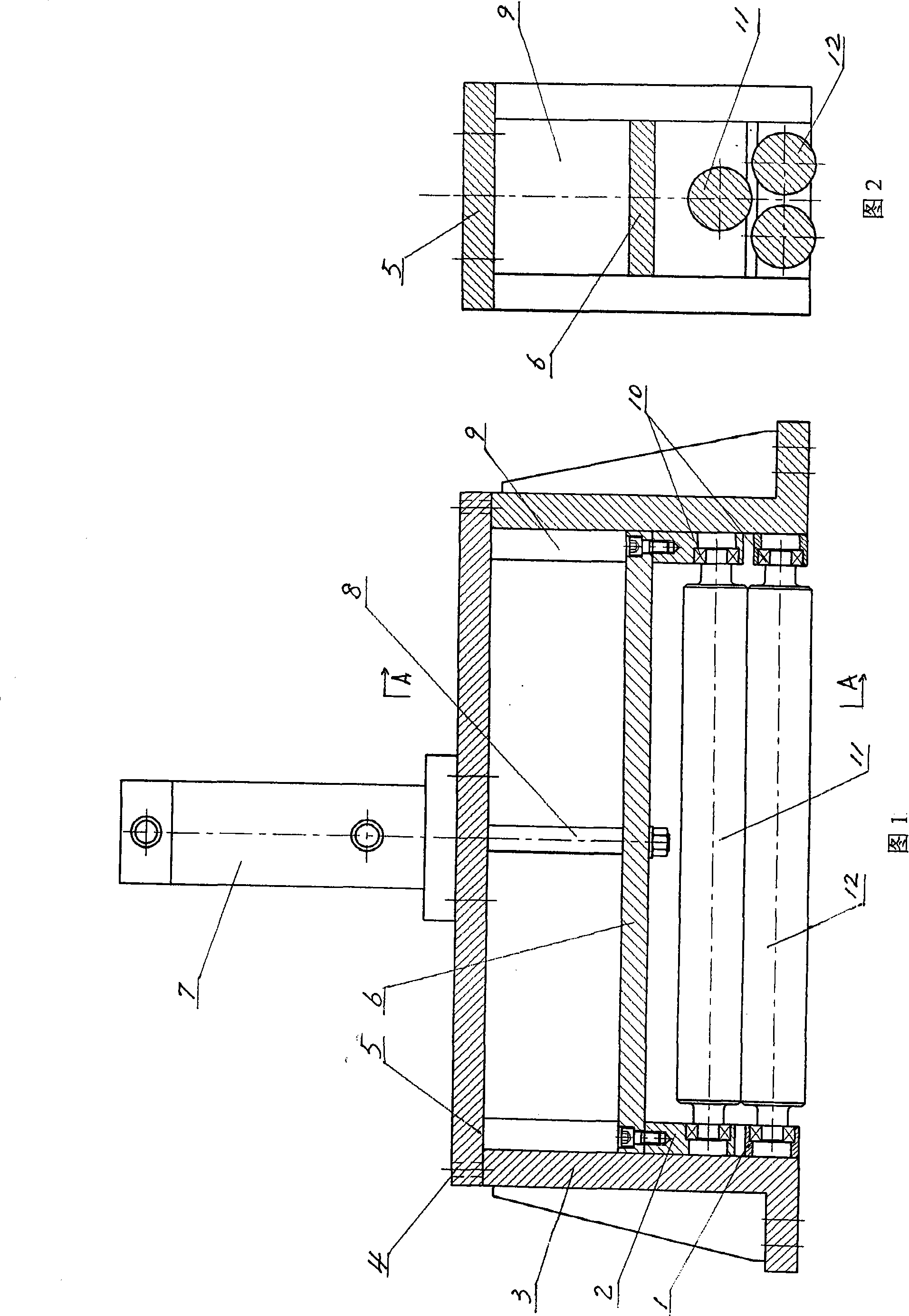
[0011] As shown in Figures 1 and 2, the hydraulic water and oil squeezing device of the present invention includes two plate-shaped supports 3, which are arranged in parallel and opposite to each other, and a gland 5 is arranged between their top ends. Both ends of the gland 5 are respectively fixed on the top ends of the two plate-shaped supports 3 by means of screws 4 . Vertical chute 9 is processed in the middle of the inner surfaces of the two plate-shaped supports 3, and upper bearing seat 2 and lower bearing seat 1 are installed in the two vertical chute, and upper bearing seat 2 can be moved along the vertical chute 9. Swipe up and down. An upper roller 11 is arranged between the two upper bearing seats 2, and the two ends of the upper roller 11 extend into the two upper bearing seats 2 by means of bearings 10 respectively. A lower roller 12 is arranged between the two lower bearing seats 1, and the two ends of the lower roller 12 extend into the two lower bearing seat...


PUM


Abstract

The invention discloses a hydraulic water or oil extruding device, used for extruding the cooling fluid on the surface of the rolled strips during the operation of mills, comprising two platy supports. The two platy supports are positioned in a parallel relative layout. The ends of the two platy supports are connected with each other through a gland bush. Vertical slideways are arranged on the center of the inner surfaces of the two supports. Upper bearing supports and lower bearing supports are arranged inside the vertical slideways. An upper roller is arranged between the upper bearing supports. Both ends of the upper roller respectively extend into the two upper bearing supports through bearings. A lower roller is arranged between the lower bearing supports. Both ends of the lower roller respectively extend into the two lower bearing supports through bearings. A hanger plate is arranged between the two upper bearing supports. Both ends of the hanger plate are respectively fixed on the upper surfaces of the two upper bearing supports. A vertical cylinder is arranged on the center of the gland bush. The cylinder rod of the cylinder extends below the gland bush, and the extending end of the cylinder rod is fixed connected with the hanger plate. The hydraulic water or oil extruding device has the advantage of improving the rolling quality of belt materials.

Description

technical field [0001] The invention relates to rolling mill matching equipment. Specifically, it is a hydraulic water and oil squeeze device used to squeeze out the cooling liquid on the surface of the rolled strip during the operation of the rolling mill. Background technique [0002] It is well known in the rolling mill manufacturing industry and the application industry that cooling liquids such as water or oil need to be continuously sprayed on the rolls in order to reduce the temperature of the rolls during the operation of the rolling mill. The coolant will adhere to the strip, causing spots such as watermarks or mimeographs to form on the surface of the strip, thereby affecting the quality of the strip. At present, there is no supporting device for removing the coolant attached to the strip on the rolling mill, so the quality of the rolled strip is not high. Contents of the invention [0003] The problem to be solved by the present invention is to provide a hydra...

Claims


Application Information

Patent Timeline
IPC IPC(8): B21B45/02
Inventor 孙大南
Owner 朱惠兴
Why Eureka
Try Eureka