Working roller for wire and bar roughing mill stand and manufacturing method thereof

A manufacturing method and technology of work rolls, which are applied in the direction of rolls, metal rolling, manufacturing tools, etc., can solve the problems of large hardness drop, large difference in internal and external performance of the working layer of the roll, and low single-rolling volume, and achieve internal and external hardness. The effect of small drop, reducing the sensitivity of the section, and improving the wear resistance of the product

Active Publication Date: 2020-05-05
邢台轧辊线棒辊有限责任公司
View PDF9 Cites 7 Cited by
  • Summary
  • Abstract
  • Description
  • Claims
  • Application Information

AI Technical Summary

Problems solved by technology

[0003] 1. The internal and external performance of the working layer of the roll is quite different. The traditional pearlitic ductile iron roll generally adopts the method of integral casting. The prepared pearlitic ductile iron roll has a very large difference in hardness inside and outside the working layer, and the hardness drop between the inside and outside of the working layer of 100mm can reach 10HSD, leading to a significant decrease in the wear resistance of the roll during use, and the online rolling use time is short, which affects the rolling efficiency
[0004] 2. Pearlitic ductile iron rolls have poor wear resistance, resulting in poor thermal crack resistance, severe thermal cracks at the bottom of the groove, low single rolling volume and affecting rolling quality
Due to the high rolling temperature and slow rolling speed of the roughing stand, the surface temperature of the roll body is high, the matrix of pearlitic ductile iron products is mainly pearlite, and the matrix strength is low. Under the continuous impact of the billet, the bottom of the roll groove is prone to heat Cracks can not maintain a good pass shape, resulting in the failure to ensure a good material shape after rough rolling, affecting the quality of subsequent rolling

Method used


Image

  • Working roller for wire and bar roughing mill stand and manufacturing method thereof
  • Working roller for wire and bar roughing mill stand and manufacturing method thereof
  • Working roller for wire and bar roughing mill stand and manufacturing method thereof

Examples


Embodiment 1

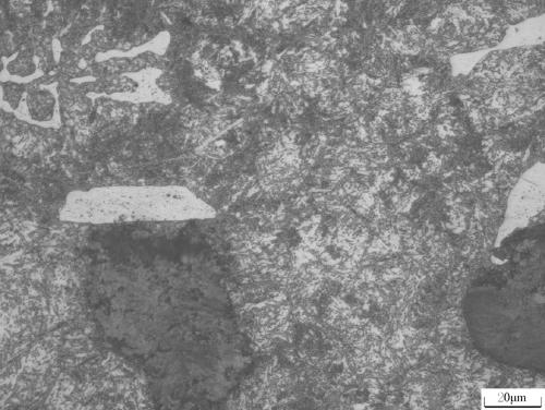
[0040] A work roll for a rough rolling stand of wire and bar, the chemical composition and the weight percentage of each component are: C 2.9-3.6%, Si 1.2-2.0%, Mn 0.3-0.8%, Cr 0.2-1.0%, Ni 1.0~2.0%, Mo 0.2~0.5%, P≤0.15, S≤0.3, the rest is Fe and unavoidable impurities;

[0041] In step b), the smelting temperature is 1440°C, the addition amount of the inoculant is 0.4%, and the addition amount of the nodulizer is 0.8% of the total amount of molten iron;

[0042] In step d): cooling at room temperature to 300°C and opening the box;

[0043] According to the furnace inspection, the chemical composition and the weight percentage of each component of the pearlitic ductile iron blank are: C3.31%, Si 1.52%, Mn 0.55%, Cr 0.31%, Ni 1.3%, Mo 0.3%, P0.15%, S 0.3%, the rest is Fe and unavoidable impurities;

[0044] In step A, the semi-finished work roll is heated to 845°C in an air furnace for heat preservation, the high-temperature quenching and heat preservation time is 12h, and th...

Embodiment 2

[0054] The process steps in this embodiment are the same as those in Example 1, and the difference from Example 1 is that the smelting temperature in step b) of this embodiment is 1460°C, the amount of inoculant added is 0.6%, and the amount of nodulizer added is molten iron 1.0% of the total amount;

[0055] In step d): cooling at room temperature to 320°C and opening the box;

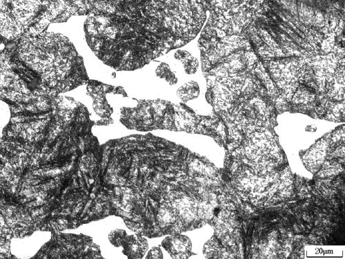
[0056] According to the furnace inspection, the chemical composition and the weight percentage of each component of the pearlitic ductile iron blank are: C3.1%, Si 1.75%, Mn 0.61%, Cr 0.63%, Ni 2.0%, Mo 0.35%, P 0.04, S≤0.2, the rest are Fe and unavoidable impurities;

[0057] In step A, the semi-finished work roll is heated to 900°C in an air furnace for heat preservation, the high-temperature quenching and heat preservation time is 6h, and the diameter φ of the semi-finished work roll body is 400mm;

[0058] In step B, the water spray pressure is 4.0MPa, and the water spray flow rate is 8.0m 3 / h...

Embodiment 3

[0067] The process steps in this embodiment are the same as those in Example 1, and the difference from Example 1 is that the smelting temperature in step b) of this embodiment is 1455°C, the amount of inoculant added is 0.8%, and the amount of nodulizer added is molten iron 1.2% of the total amount;

[0068] In step d): cooling at room temperature to 320°C and opening the box;

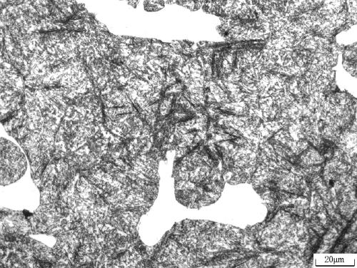
[0069] According to the furnace inspection, the chemical composition and the weight percentage of each component of the pearlitic ductile iron blank are: C3.4%, Si 1.85%, Mn 0.6%, Cr 0.41%, Ni 1.84%, Mo 0.25%, P 0.04, S≤0.2, the rest are Fe and unavoidable impurities;

[0070] In step A, the semi-finished work roll is heated to 920°C in an air furnace for heat preservation, the high-temperature quenching and heat preservation time is 2h, and the diameter φ of the semi-finished work roll body is 610mm;

[0071] In step B, the water spray pressure is 4.0MPa, and the water spray flow rate is 8.0m 3 / h...


PUM

PropertyMeasurementUnit
tensile strengthaaaaaaaaaa

Abstract

The invention discloses a working roller for a wire and bar roughing mill stand. The working roller comprises, by weight, 2.9-3.6% of C, 1.2-2.0% of Si, 0.3-0.8% of Mn, 0.2-1.0% of Cr, 1.0-2.0% of Ni,0.2-0.5% of Mo, less than or equal to 0.15% of P, less than or equal to 0.3% of S, and the balance being Fe and inevitable impurities. A manufacturing method is characterized in that a pearlitic ductile cast iron blank manufactured through integral casting is subjected to rough machining and then quenching heat treatment to obtain the working roller with the structure of bainite, tempered sorbiteand carbide for the roughing mill stand. The pearlitic ductile cast iron blank manufactured through integral casting is subjected to rough machining and then quenching heat treatment, so that not only is the hardness drop inside and outside a working layer reduced, but also the wear resistance is improved, and the probability of occurrence of hot cracks at the bottom of a roller groove is reduced.

Description

technical field [0001] The invention relates to a work roll for a wire and bar rough rolling stand and a manufacturing method thereof, belonging to the technical field of steel rolling. Background technique [0002] In recent years, with the development of high-speed and continuous rolling of wire and bar mills at home and abroad, and the continuous improvement of rolled materials, steel mills have higher and higher requirements for roll applicability. The rough rolling stand has the characteristics of high rolling temperature, low rolling speed and large reduction. Especially in recent years, the length of the rolled material is long and the rough rolling roll is heated for a long time. Therefore, it is not only required that the roll has good wear resistance and high strength. , but also have better thermal crack resistance and toughness. At present, the traditional pearlitic ductile iron rolls are generally used for the rough rolling stand of wire and bar. The following ...

Claims


Application Information

Patent Timeline
Patent Type & Authority Applications(China)
IPC IPC(8): C22C37/10C22C37/06C22C37/04C21D1/18C21D5/00C21D9/38C21C1/10C22C33/08B21B27/00
CPCB21B27/00C21C1/10C21D1/18C21D5/00C21D9/38C21D2211/00C21D2211/002C21D2211/004C22C33/08C22C37/04C22C37/06C22C37/10
Inventor 马大江董亮张恒波李晓刚
Owner 邢台轧辊线棒辊有限责任公司
Why Eureka
Try Eureka