Clamping type feedback lever

A feedback lever and clamping technology, which is applied in the direction of fluid pressure actuators, servo motor components, mechanical equipment, etc., can solve the problems of high manufacturing precision, difficult machining, and hidden dangers of falling off, so as to reduce processing difficulty, The effect of eliminating bad influence and eliminating negative influence

Inactive Publication Date: 2008-08-20
中国船舶重工集团公司第七0四研究所
View PDF0 Cites 5 Cited by
  • Summary
  • Abstract
  • Description
  • Claims
  • Application Information

AI Technical Summary

Problems solved by technology

[0003] 1. The size of the small ball is small, and the small gap between the small ball and the spool housing hole requires high manufacturing precision, so machining is difficult and the production cost increases accordingly;
[0004] 2. During the working process, the ball and the spool slide to form wear, and the wear forms a gap between the ball and the spool accommodating hole, and the increase of the gap will affect the operating performance of the servo valve
[0005] 3. It is difficult to maintain after the ball is worn out, and usually needs to be reprocessed, which increases maintenance costs;
[0006] 4. When the feedback rod and the ball are welded, there is a risk of falling off

Method used


Image

  • Clamping type feedback lever

Examples


Embodiment Construction

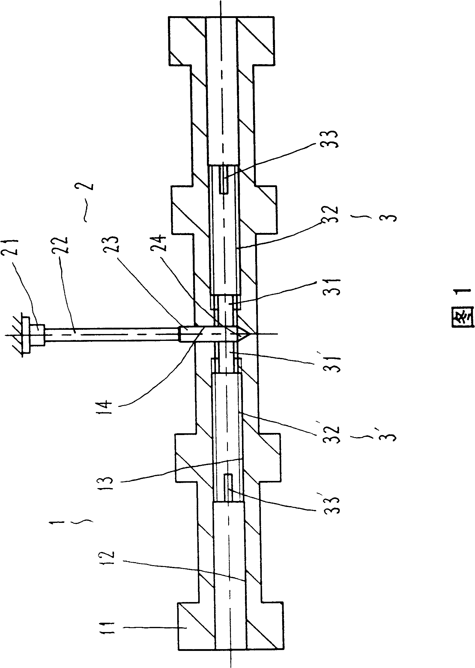
[0011] Referring to Fig. 1, the clamping feedback lever includes a spool 1, a feedback lever 2 and two clamping screws 3, 3'.

[0012] The valve core 1 has the same or similar external structure as the existing structure. The feature of the present invention is that a through hole 12 is arranged on the axial center line of the valve core body 11 of the valve core 1, and the diameter of the middle part of the through hole 12 is slightly smaller. A screw hole 13 is provided, and the screw hole 13 can also be a symmetrical section, and a through hole with a diameter slightly larger or the same as the thread root diameter of the screw hole 13 is connected between the two sections, and an accommodating hole is arranged in the middle of the through hole 12 14. The center line of the receiving hole 14 is perpendicular to the center line of the through hole 12 and intersects. The receiving hole 14 passes through the through hole 12 and a tapered hole is drilled on its inner wall.

[0...


PUM


Abstract

The invention provides a clamp typed feedback rod which mainly solves the technical problems of improving manufacture process and enhancing the performance of a servo valve, etc. The technical proposal of the clamp typed feedback rod is that a valve core is provided with a screw hole in the axial direction; one end of the feedback rod passes through the valve core and vertically passes through the screw hole; two clamping screws are respectively screwed in the screw hole; the ends of the two clamping screws respectively pushes against the external surface at the two sides of the feedback rod. the clamp typed feedback rod is suitable for various electro-hydraulic servo valves.

Description

Technical field: [0001] The invention relates to an electro-hydraulic servo valve, in particular to a component of the electro-hydraulic servo valve. Background technique: [0002] The electro-hydraulic servo valve is a servo control element in hydraulic engineering. Its feedback torque transmission structure is usually provided with a housing hole on the valve core, and the end of the feedback rod is inserted in the housing hole. The feedback rod One end of the valve is fixed, when the valve core moves, the valve core pushes the end of the feedback rod, so that the feedback rod produces elastic deformation, thereby forming a feedback torque. In view of this feature, the end of the feedback rod of the existing electro-hydraulic servo valve is made into a shape The small ball is inserted in the valve core, and its structural features are that the ball and the rod body are integrally processed and formed, and there is also a structure in which the formed small ball is welded t...

Claims


Application Information

Patent Timeline
Patent Type & Authority Applications(China)
IPC IPC(8): F15B13/044
Inventor 黄增方群王学星
Owner 中国船舶重工集团公司第七0四研究所
Why Eureka
Try Eureka