Image forming apparatus
An image and toner image technology, which is applied in the field of image forming devices, can solve the problems of complex motion control, change of transfer position, complexity, etc., achieve simple structure, improve the accuracy of transfer position, and save space
- Summary
- Abstract
- Description
- Claims
- Application Information
AI Technical Summary
Problems solved by technology
Method used
Image
Examples
no. 1 approach
[0096] Hereinafter, embodiments of the present invention will be described in detail with reference to the drawings.
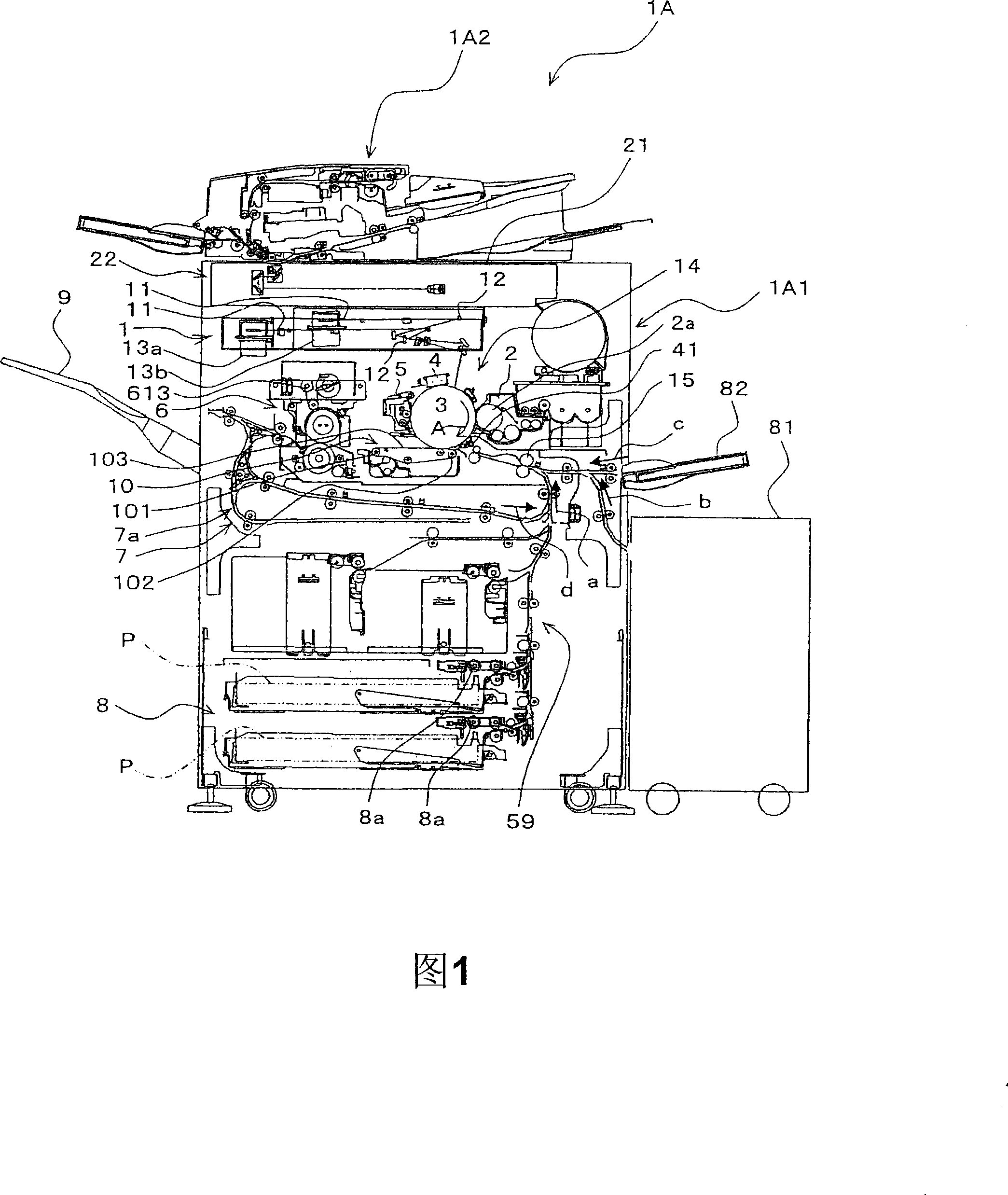
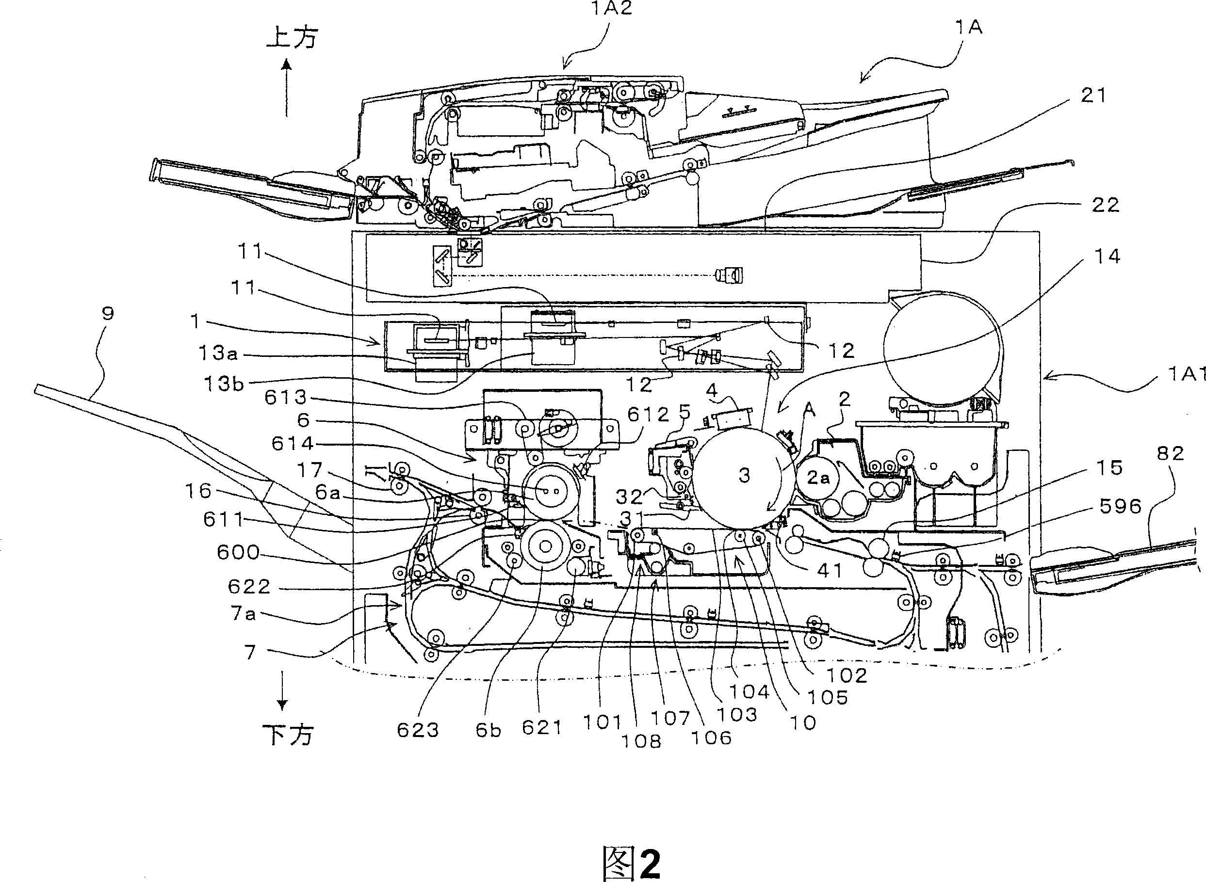
[0097] FIG. 1 is an explanatory view showing the overall structure of an image forming apparatus employing a paper conveying device according to the present invention, and FIG. 2 is a partial detailed view showing the structure of the main body of the image forming apparatus.
[0098] The image forming apparatus 1A of this embodiment outputs image data read by a scanner or the like or image data transmitted from the outside as a monochrome image by electrophotography and forms it on a predetermined sheet-shaped recording medium as a recording medium. paper (hereinafter referred to as paper).
[0099] The image forming apparatus 1A includes an image forming unit 14 , a developer (developing unit) 2 , a registration roller (recording medium transport unit) 15 , and a drive control unit (control unit) 62 (see FIG. 6 ).
[0100] The image forming unit 14 includes...
no. 2 approach
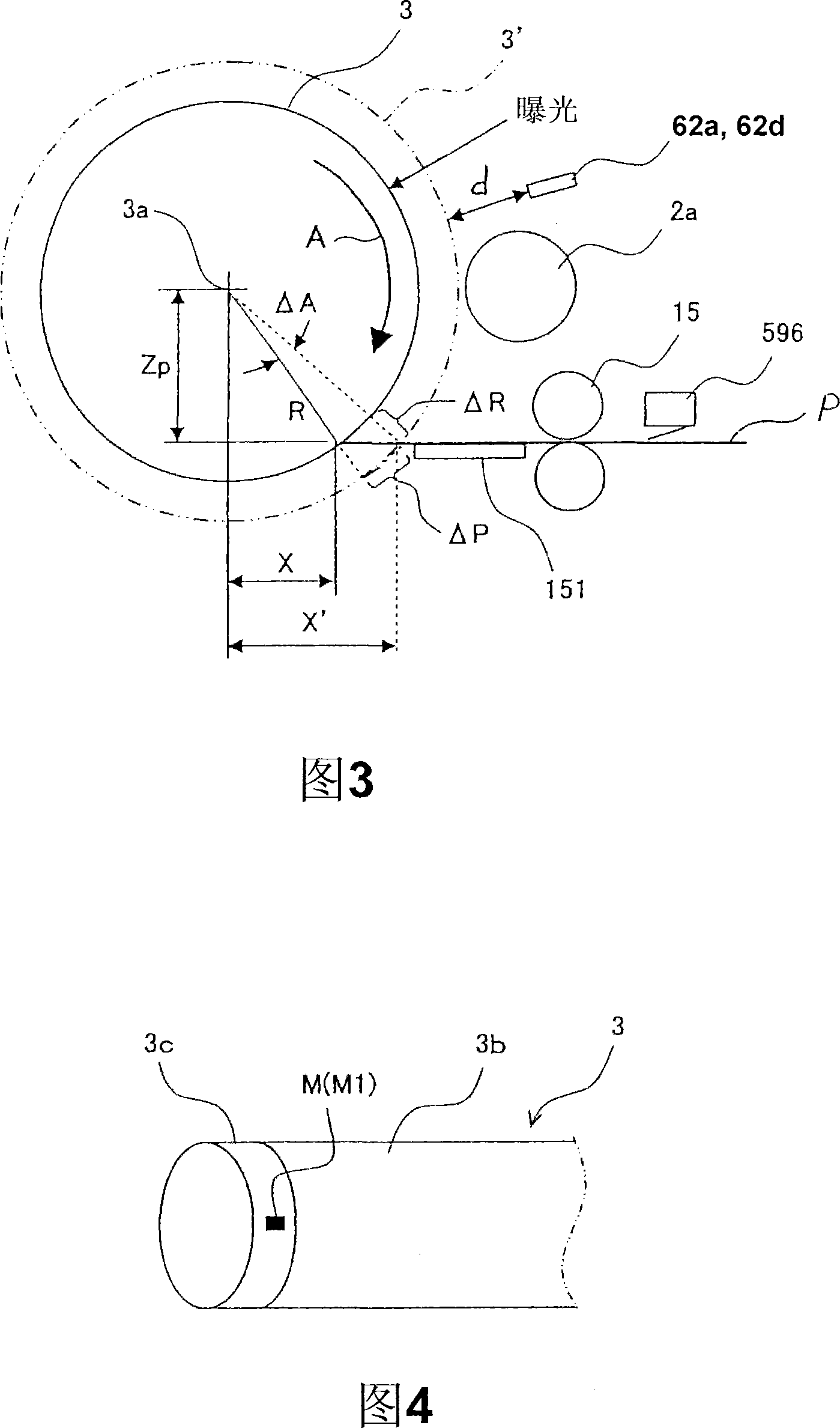
[0244] 1 to 3 and FIG. 7 are common drawings for the first and second embodiments, and description thereof will be omitted. In addition, the same structure as the structure of the said 1st Embodiment is attached|subjected with the same code|symbol, and the description is abbreviate|omitted.
[0245] 10 is an explanatory view showing a detection area detected by a phase sensor on the outer peripheral surface of the photosensitive drum according to the second embodiment.
[0246] On the outer peripheral surface of the photosensitive drum 3, as shown in FIG. Marked with M and barcode Mb. The region where the mark M and the barcode Mb are formed becomes a detection region.
[0247] Information on the photosensitive drum 3 is recorded in the barcode Mb, that is, the rotational phase of the photosensitive drum relative to the mark M (rotational phase information), the amount of eccentricity of the position corresponding to the rotational phase (eccentricity information), the posit...
PUM
| Property | Measurement | Unit |
|---|---|---|
| Resistance | aaaaa | aaaaa |
| Diameter size | aaaaa | aaaaa |
Abstract
Description
Claims
Application Information
 - R&D
- Intellectual Property
- Life Sciences
- Materials
- Tech Scout
- Unparalleled Data Quality
- Higher Quality Content
- 60% Fewer Hallucinations
Browse by: Latest US Patents, China's latest patents, Technical Efficacy Thesaurus, Application Domain, Technology Topic, Popular Technical Reports.
© 2025 PatSnap. All rights reserved.Legal|Privacy policy|Modern Slavery Act Transparency Statement|Sitemap|About US| Contact US: help@patsnap.com


