

Base plate with radiating structure
A heat dissipation structure and shaft tube technology, which is applied in the cooling of instruments, parts of instruments, cooling/ventilation/heating transformation, etc., to reduce product failure rate, prevent shaft tube deflection, and prolong service life
- Summary
- Abstract
- Description
- Claims
- Application Information
AI Technical Summary
Problems solved by technology
Method used
Image

Examples
Embodiment Construction
[0045] The structure and effect of the present invention will be described in detail by citing the following embodiments in conjunction with the accompanying drawings.
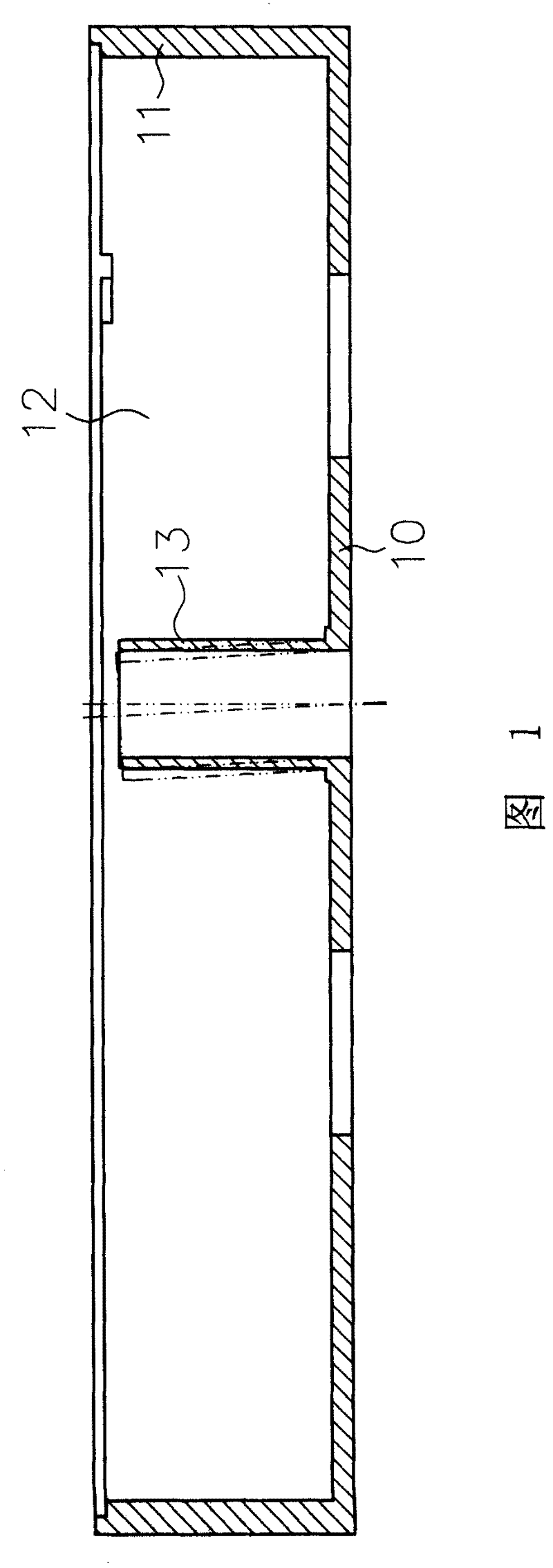
[0046] The invention relates to a base of a heat dissipation structure, which is provided with a groove on the base, and the groove is located outside the outer diameter of the shaft tube. The design of the groove can effectively block the influence of the internal stress of the cooling contraction on the shaft tube, avoiding Shaft tube deflection improves product quality and life.
[0047] Several preferred implementation forms of the present invention are listed below for illustration.
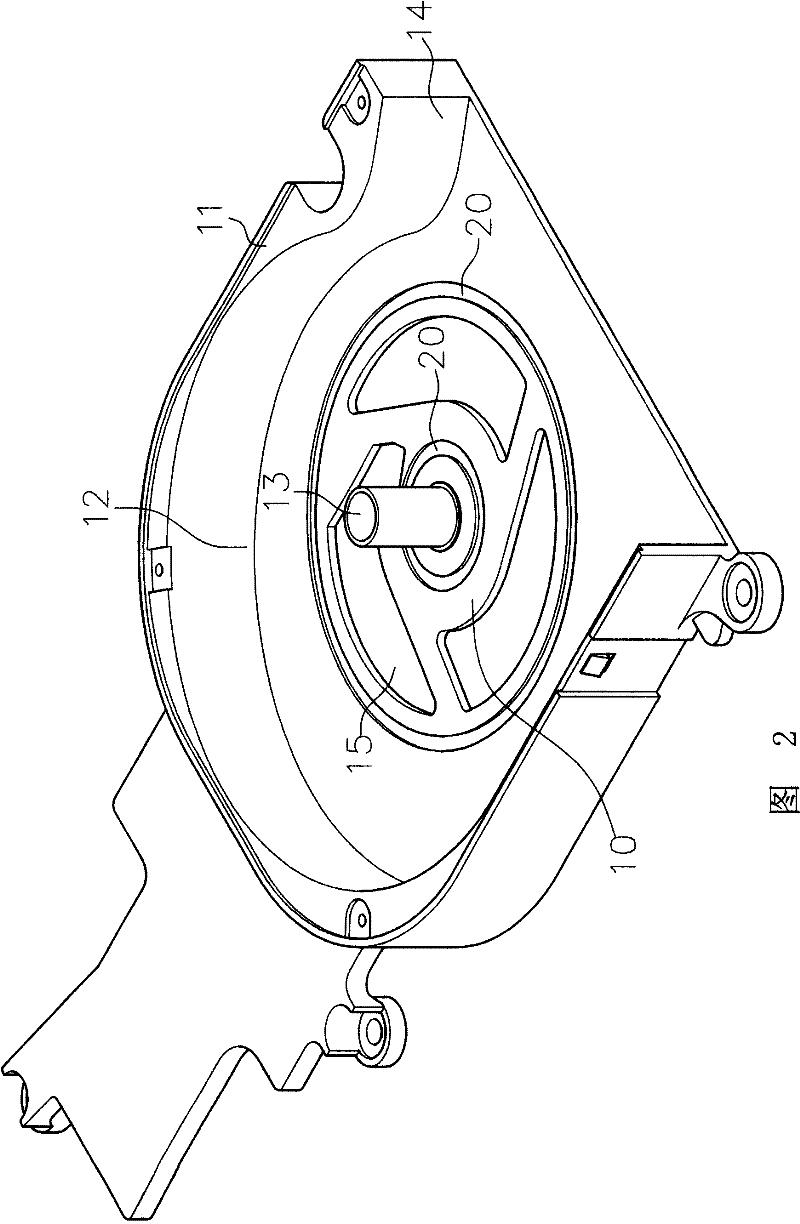
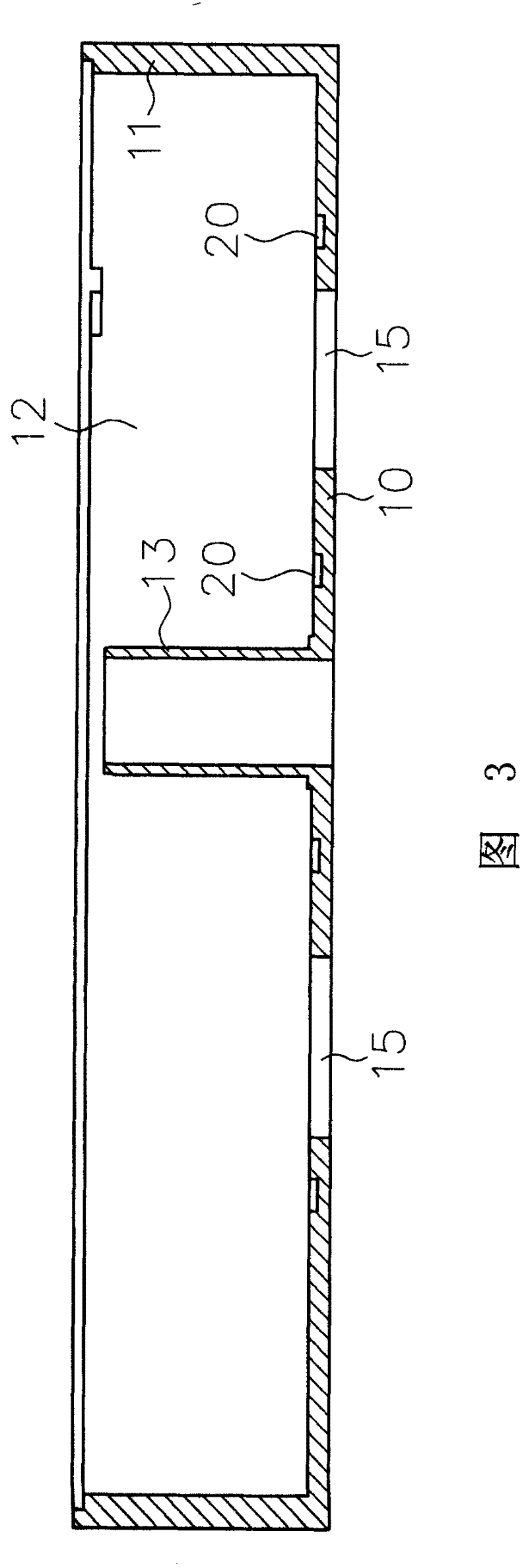
[0048] Such as figure 2 , image 3 As shown, it is the first embodiment of the present invention, which includes:
[0049] A base 10, except for the air outlet side 14, is surrounded by side walls 11 to form an accommodating space 12. A fan wheel and a stator group (not shown) are arranged inside the accommodating space ...
PUM
 Abstract
Description
Claims
Application Information