Eureka AIR delivers breakthrough ideas for toughest innovation challenges, trusted by R&D personnel around the world.

Control system for micro-nano sample in electronic microscope

An electron microscope and control system technology, applied in circuits, discharge tubes, electrical components, etc., can solve the problems of limited space, increased repeated testing and personalized modification, and decreased automatic operation ability, so as to achieve easy operation and avoid affecting the vacuum degree. and test accuracy, the effect that is conducive to observation

Inactive Publication Date: 2011-06-15
苏州特尔纳米技术有限公司
View PDF2 Cites 0 Cited by
  • Summary
  • Abstract
  • Description
  • Claims
  • Application Information

AI Technical Summary

Problems solved by technology

[0007] At present, the input and output commands of the control system are connected to the control circuit on the operating platform through the wires passing through the sample room, and holes are reserved on the side wall of the sample room for connection. The resulting problems are: ① test The sample chamber needs to maintain a vacuum state (10 -7 torr), a sealing device that can ensure the vacuum degree of the sample chamber needs to be installed in the channel where the wires pass through, and when there are more operating modules, there will be more input and output wires corresponding to each module, which will affect the production of the sealing device. Considerable difficulties, and the vacuum degree in the sample chamber is one of the key factors affecting the imaging quality of the microscope; ②The position and number of holes reserved on the side wall of the sample chamber on different types of electron microscopes are inconsistent. When the control system and the microscope During assembly, it is necessary to refit the sample room, reconnect the control circuits, and maintain the consistency of the test environment in the sample room, thus increasing the trouble of repeated testing and personalized modification; ③The space in the sample room is limited, and the size is as follows: 15cm×15cm×6cm, in such a limited space, it is necessary to set up a control system (including various operating modules, sample stages, etc.), and the space for the control circuit and input and output command lines to be connected is limited, so the sample executes each The number of instruction line access and setting operation modules required for such complex operations is limited, and the ability of automatic operation is reduced, which brings inconvenience to research and measurement work

Method used


Image

  • Control system for micro-nano sample in electronic microscope
  • Control system for micro-nano sample in electronic microscope
  • Control system for micro-nano sample in electronic microscope

Examples


Embodiment 1

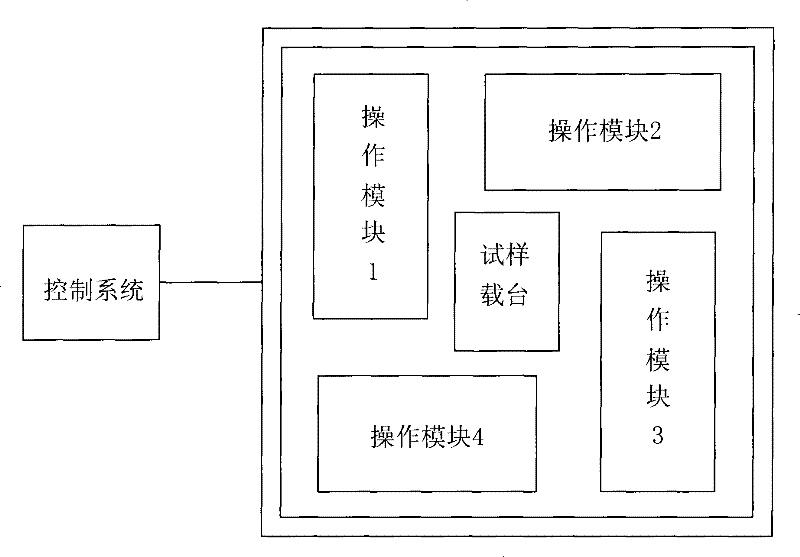
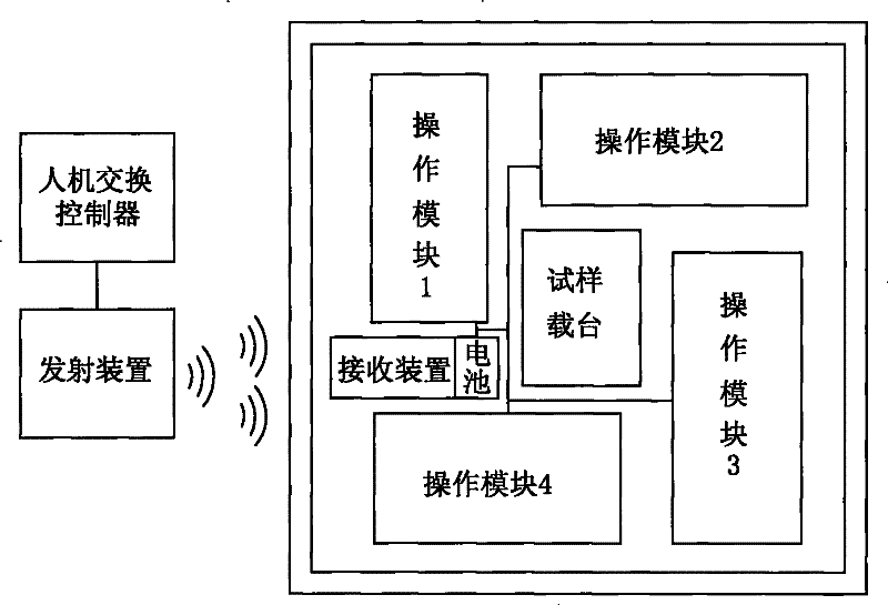
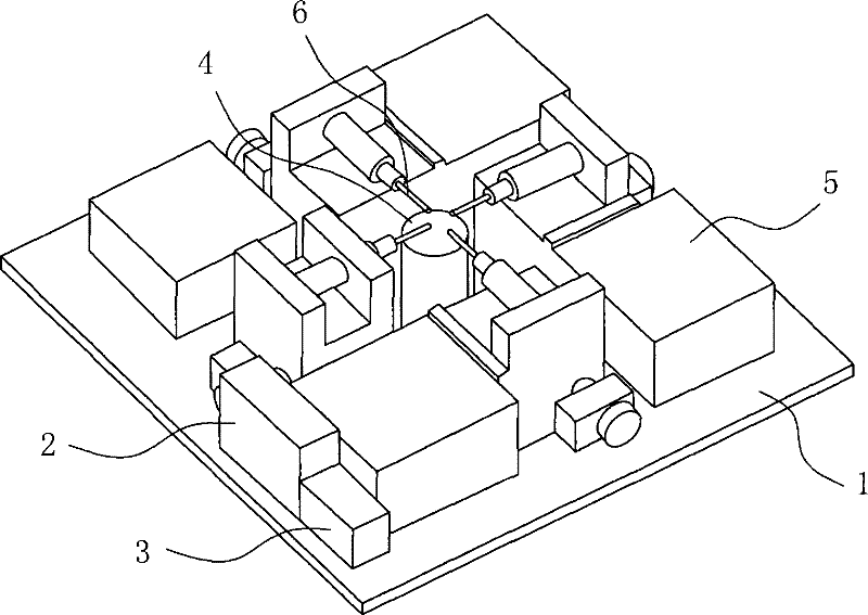
[0024] Embodiment one: see Figure 1 to Figure 3 As shown, a control system for micro-nano samples under an electron microscope includes an operating platform 1, 4 operating modules 5 arranged on the platform, a sample carrier 4 for carrying samples, and each operating module 5 A control device connected to a control circuit, the control device includes a signal transmitting device, a signal receiving device 2 and a battery assembly 3 compatible with a vacuum environment, the signal receiving device 2 is arranged on the operating platform 1, and its signal The output end is connected to each of the control circuits, the signal transmitting device is connected to a man-machine exchange control, and sends a radio frequency (RF) signal to the signal receiving device 2 through radio waves, the battery assembly 3 is a solid battery, Its output terminal is connected with each control circuit and the power supply terminal of the signal receiving device 2 to supply power to the receiv...

Embodiment 2

[0026] Embodiment two: see Figure 4As shown, a control system for micro-nano samples under an electron microscope includes an operating platform, an operating module set on the platform, a sample carrier carrying samples, and a control device connected to the control circuit in the operating module , the control device includes a signal transmitting device, a signal receiving device and a battery assembly compatible with a vacuum environment, the signal receiving device is arranged on the operating platform, and the battery assembly is composed of a liquid battery and a sealed battery wrapped outside the battery The liquid battery and the sealed case are filled with air, and the electrode terminals of the battery are led out of the sealed case through wires, connected to the receiving device and the power supply end of the control circuit, and supply power to both. The signal output terminal of the device is connected with the control circuit, the signal transmitting device i...


PUM


Abstract

The present invention discloses a control system for micro-nano samples under electron microscopes, comprising an operation platform, a sample carrier, operation modules and a control device. The control system is characterized in that: the control device comprises a signal transmitting device, a signal receiving device and a battery component compatible with vacuum environment; the signal receiving device is arranged on the operation platform; the signal transmitting device is connected with a human-computer exchange controller and transmits control signals to the signal receiving device through wireless transmission medium; the battery component supplies power to the receiving device and a control circuit; the receiving device receives signals and drives the operation modules to executecorresponding operation via the control circuit. Through the fit of the signal transmitting device and the receiving device, the present invention uses the wireless transmission medium as a communication mode, so as to realize the wireless control on the operation modules in a sample chamber and prevent conductor interpenetration and sample chamber refitting from affecting the vacuum degree of the sample chamber. The control system is suitable for various electron microscopes, and is direct and convenient to operate.

Description

technical field [0001] The invention relates to a control system for observing and processing micro-nano samples, in particular to a control system for manipulating micro-nano samples to perform various operations under an electron microscope. Background technique [0002] An electron microscope is an instrument that uses electron beams and electron lenses instead of light beams and optical lenses to image the fine structures of substances at very high magnifications based on the principle of electron optics. Indicated by the minimum spacing. The maximum magnification of a modern electron microscope exceeds 3 million times, while the maximum magnification of an optical microscope is about 2000 times (this is limited by the wavelength of light on which the microscope performs its work), so certain things can be directly observed through an electron microscope. Atoms of heavy metals and neatly arranged atomic lattices in crystals. [0003] Modern electron microscopes general...

Claims


Application Information

Patent Timeline
Patent Type & Authority Patents(China)
IPC IPC(8): H01J37/20G01Q30/20
Inventor 杨毅华张卫侯蓉晖
Owner 苏州特尔纳米技术有限公司
Why Eureka
Eureka Blog
Learn More