

Wall structure
A technology for walls and structural components, applied in the direction of walls, building components, building structures, etc., can solve the problems of floor impact sound reduction effect and small rigidity strengthening effect of planar components, etc.
- Summary
- Abstract
- Description
- Claims
- Application Information
AI Technical Summary
Problems solved by technology
Method used
Image

Examples
no. 1 approach
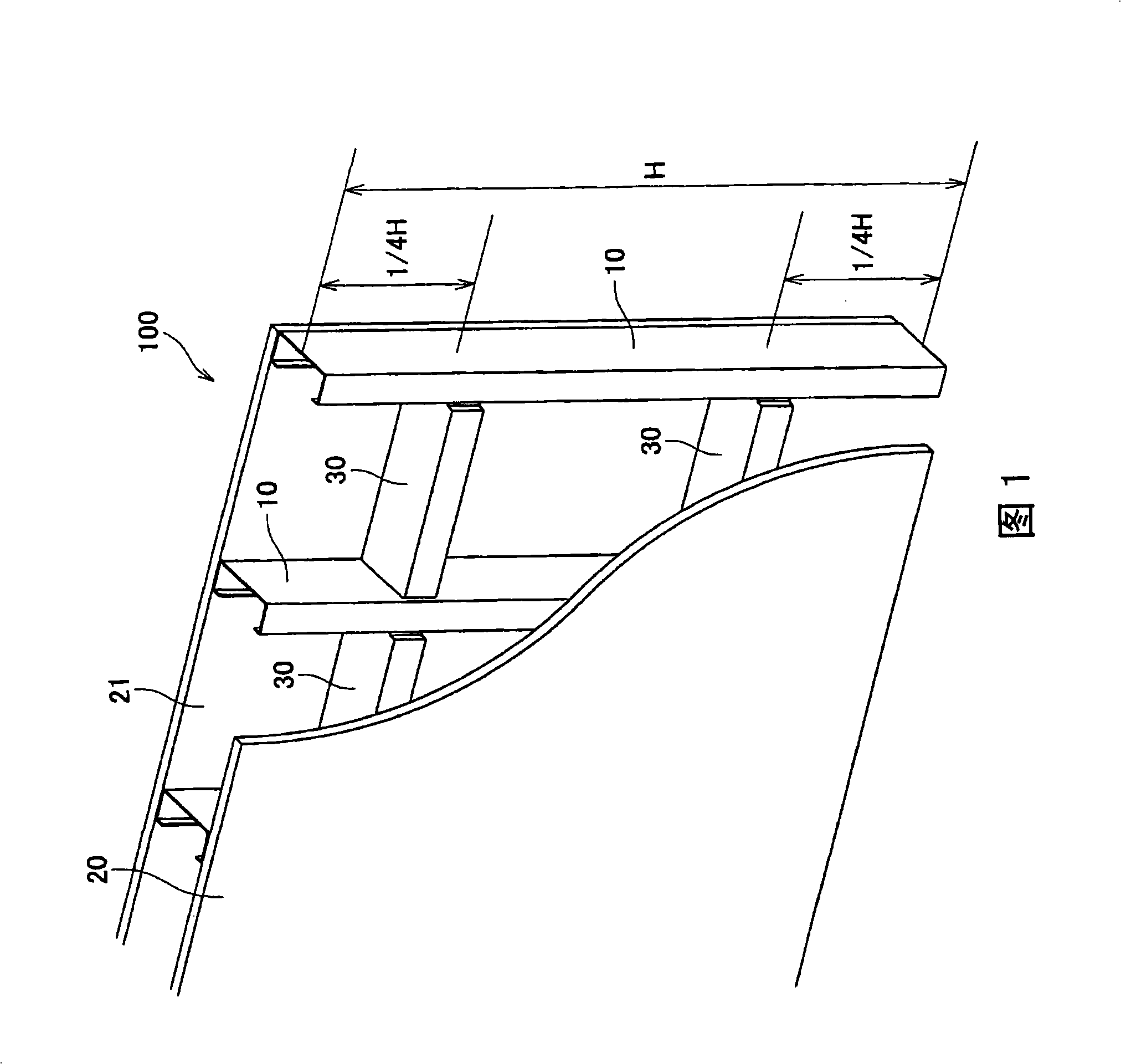
[0044] FIG. 1 is a schematic perspective view showing an example of a wall structure 100 according to an embodiment of the present invention.
[0045] As shown in FIG. 1, the wall structure 100 includes a vertical frame 10, gypsum boards 20 and 21 and a connecting member 30.
[0046] As shown in FIG. 1, a plurality of vertical frames 10 are arranged on a straight line at predetermined intervals, and a gypsum board 20 is fixed on one side of the plurality of vertical frames 10 with screws (refer to FIG. 5), and on the other side of the plurality of vertical frames 10 The gypsum board 21 is fixed and installed with screws (refer to FIG. 5).
[0047] As shown in FIG. 1, if the vertical length from the upper end to the lower end of the plurality of vertical frames 10 is H, the connecting member 30 is provided at a distance of 1 / 4×H from the upper end of the vertical frame 10, and the connecting member 30 is installed at a distance of 1 / 4×H from the upper end of the vertical frame 10. ...
no. 2 approach
[0075] 11 is a schematic cross-sectional view showing an example of the connection state of the vertical frame 10 and the connecting member in the wall structure 100b of the second embodiment, FIG. 12 is a schematic cross-sectional view showing a comparative example of the wall structure 100b of FIG. 11, and FIG. 13 is A schematic cross-sectional view showing another example of the wall structure 100b of the second embodiment.
[0076] The wall structure 100z in FIG. 12 includes vertical frames 10 and 11 and gypsum boards 20, 21, 22, and 23. In addition, the wall structure 100b shown in FIG. 11 includes vertical frames 10, 11, gypsum boards 20, 21, 22, 23, and connecting members 31a, 31b.
[0077] As shown in FIGS. 11 and 12, the gypsum boards 20 and 22 are laminated and the gypsum boards 21 and 23 are laminated and arranged. In addition, a plurality of vertical frames 10 and 11 are arranged in a zigzag shape in the space formed by the gypsum boards 20 and 22 and the gypsum boards...
no. 3 approach
[0085] Figure 14 It is a schematic perspective view showing an example of the wall structure 100c of the third embodiment, Figure 15 Yes means Figure 14 The model front view of the wall structure 100c with the gypsum boards 20 and 21 removed, FIG. 16 shows Figure 14 A model top cross-sectional view of the wall structure 100c.
[0086] Such as Figure 14 As shown, the wall structure 100c includes a plurality of vertical frames 10, gypsum boards 20, 21, and connecting members 30c, 30d.
[0087] Figure 14 One end of the connecting member 30c shown is connected to the upper end of the plurality of vertical frames 10, and the other end of the connecting member 30c is connected to the center portion of the plurality of vertical frames 10 (if the entire height is H, it is 1 / 2×H The height of Figure 15 )connection.
[0088] On the other hand, one end of the connecting member 30d is connected to the lower end of the plurality of vertical frames 10, and the other end of the connecti...
PUM
 Abstract
Description
Claims
Application Information