

Electromagnetic contactor
A technology of electromagnetic contactor and electromagnet, which is applied in the direction of relays, electromagnets, and electromagnets with armatures, etc., and can solve problems such as repeated impacts and large impact sounds
- Summary
- Abstract
- Description
- Claims
- Application Information
AI Technical Summary
Problems solved by technology
Method used
Image

Examples
Embodiment 1
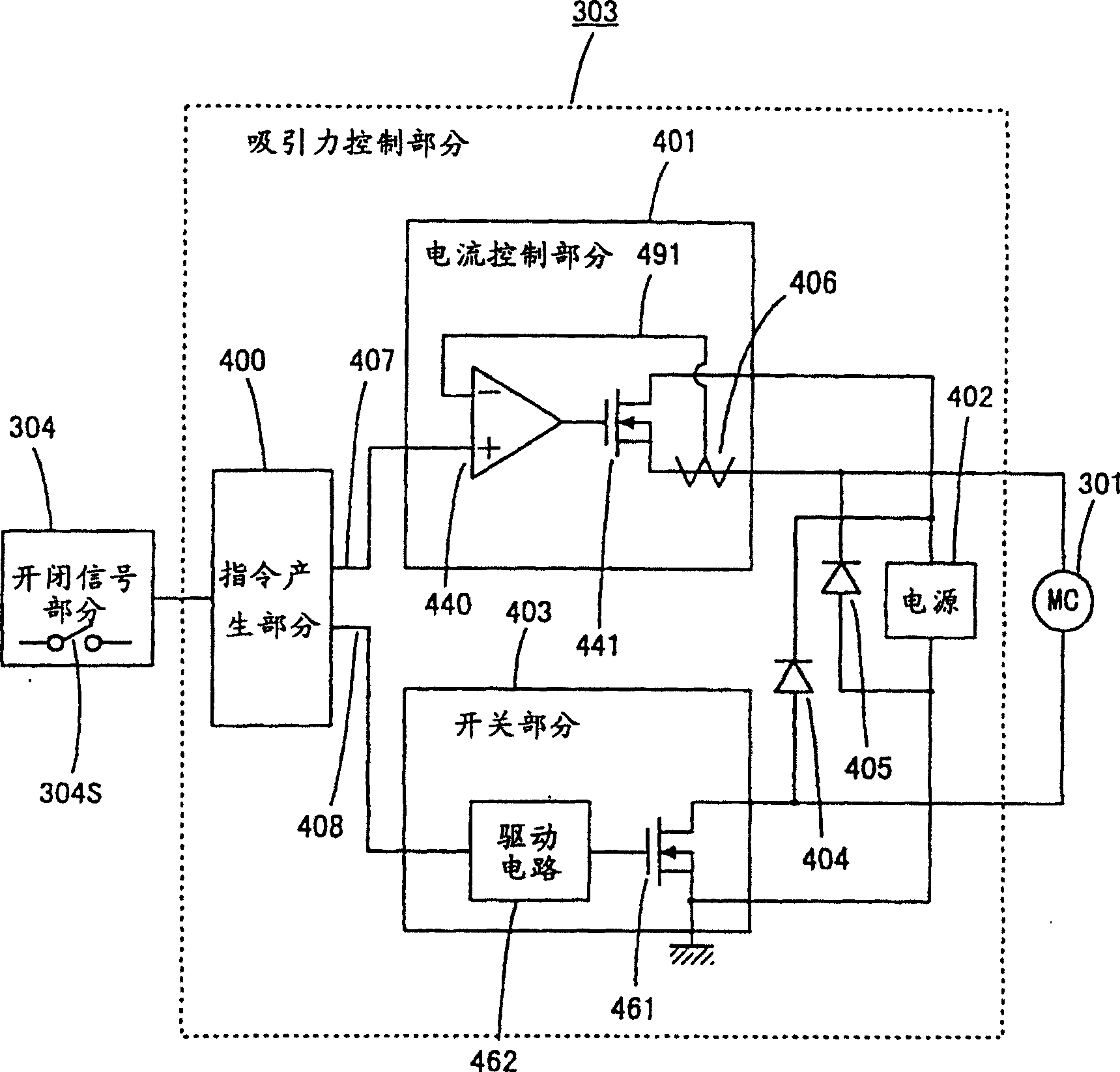
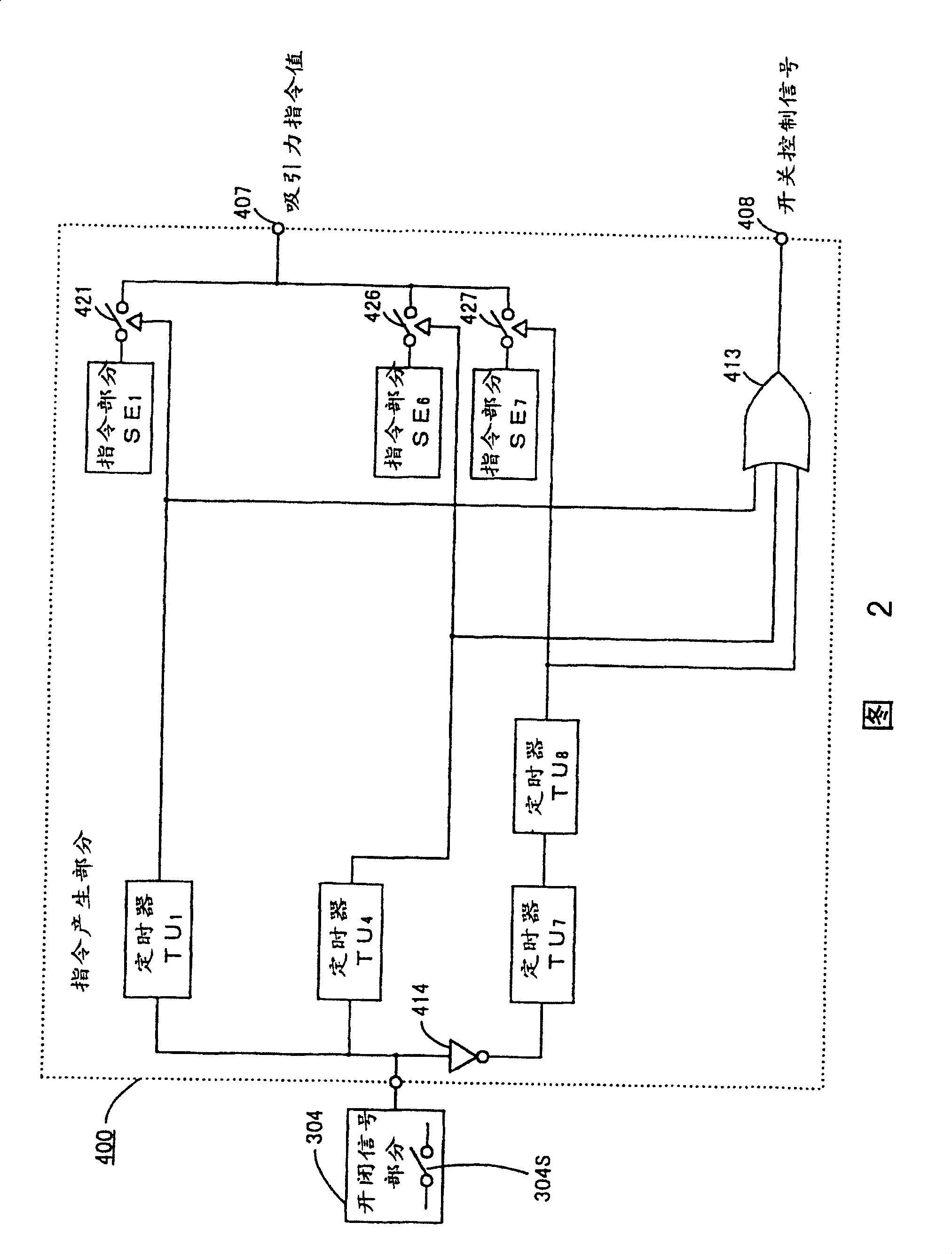
[0046] refer to figure 1 And Fig. 2 illustrates the embodiment of the present invention. figure 1 It is a block diagram representing an overall connection of an embodiment of the present invention, and Fig. 2 is figure 1 A detailed internal circuit diagram of the instruction generation section is shown. exist figure 1 And in Fig. 2, it is composed of a switch signal part 304 and an attraction control part 303, and the switch signal part 314 makes the switch 304S generate closing and opening Figure 19 The signal of the current of the electromagnet 301 (coil 21) of the electromagnetic contactor 100 shown, the described attraction force control part 303 controls the force flowing through the electromagnet 301 according to the switch signal from the switch signal part 304 as the force control means. The integral value of the current, thereby controlling the electromagnetic attraction force of the electromagnet 301.
[0047] The attractive force control section 303 is compo...
Embodiment 2
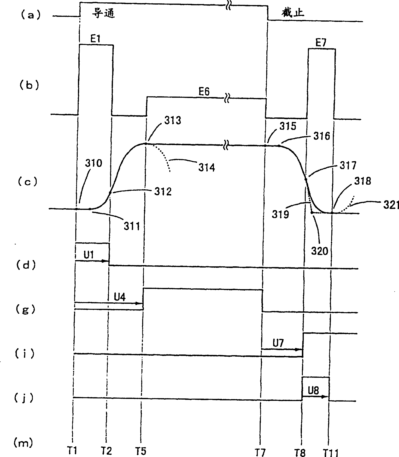
[0072] refer to figure 1 And FIG. 5 illustrates other embodiments of the present invention. Figure 5 is figure 1 The internal wiring diagram of the instruction generation section is shown. In the above example, the image 3 When the current flowing in the middle time T4 is the magnitude of the holding current, the attraction between the movable iron core 1 and the fixed iron core 20 may not be sufficient due to the electromagnetic attraction force of the fixed iron core 20 and the deviation of the trip spring 30 . Here, an embodiment of the invention improving this aspect is described.
[0073] In FIG. 5, the command generation part 400 adds the second current command part 400a to the command generation part shown in FIG. The instruction value is connected to the output, and the output signal of the timer TU4 and the output signal of the timer TU5 are inverted by the "NOT" circuit 415, and the logical product is obtained through the "OR" circuit 416, and according to the...
Embodiment 3
[0080] refer to figure 1 And FIG. 7 illustrates other embodiments of the present invention. Fig. 7 is an internal wiring diagram of the instruction generation part. In Embodiments 1 and 2 above, since the movable iron core 1 moves to the first or second position at a high speed, it was found that a shock occurs when the electromagnetic contactor is closed or opened due to deviations such as voltage fluctuations.
[0081] Here, the embodiment of the present invention is to reduce the final acceleration when closing or releasing the movable iron core 1 in order to solve the above-mentioned problems. In FIG. 7, the instruction generating section 400 changes the timer TU1 of the above-mentioned instruction generating section shown in FIG. For the timer TU18 having a time U18 slightly shorter than its set time, the current command part 400c of the weak acceleration current E3, the current command part 400e of the weak deceleration current E7, the output of the timer T3 and the t...
PUM
 Abstract
Description
Claims
Application Information