Mounting structure for variable nozzle mechanism
A technology for mounting structures and nozzles, applied to mechanical equipment, engine components, combustion engines, etc., can solve problems such as damage, elongated scroll tube 11, and deburring
- Summary
- Abstract
- Description
- Claims
- Application Information
AI Technical Summary
Problems solved by technology
Method used
Image
Examples
Embodiment 1
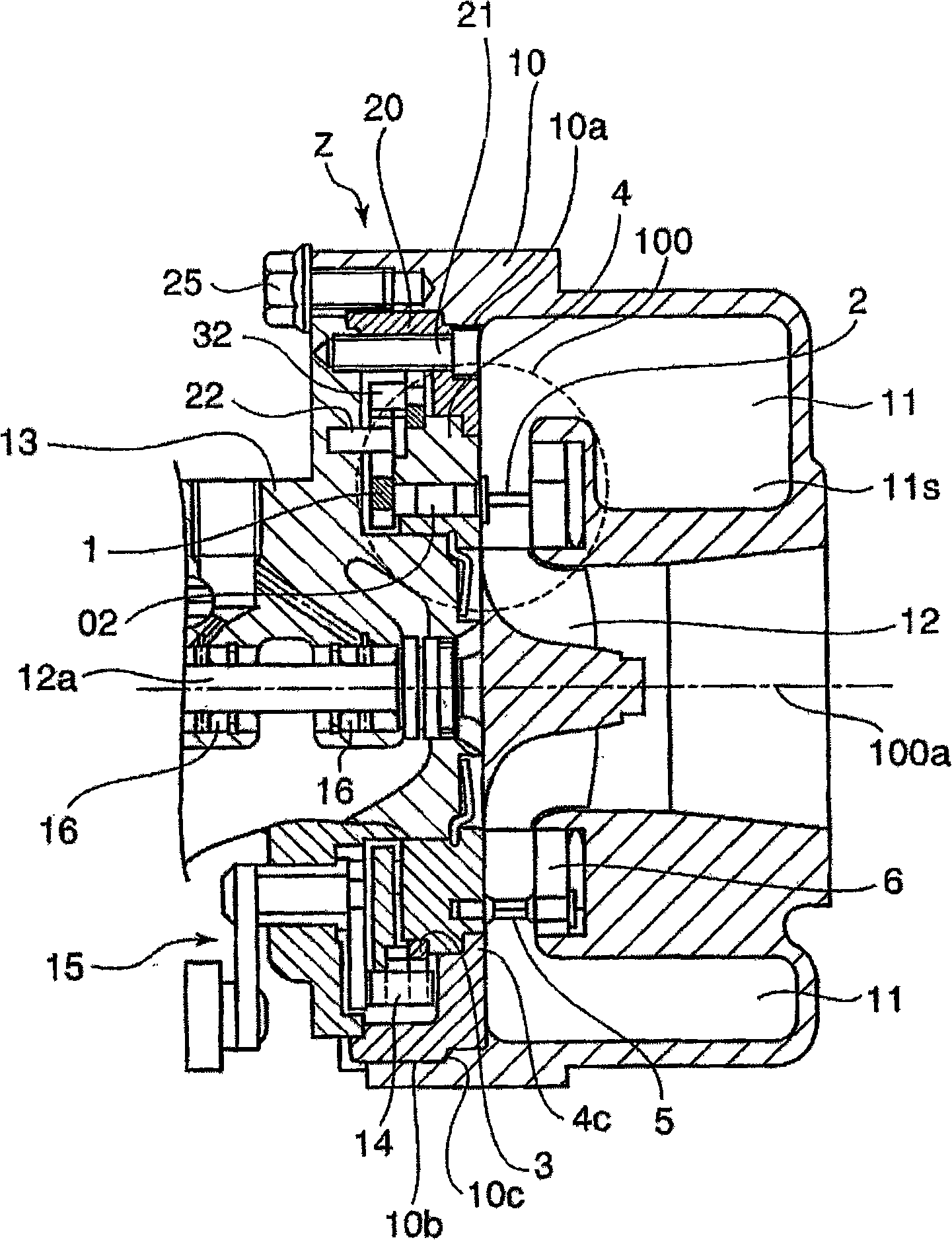
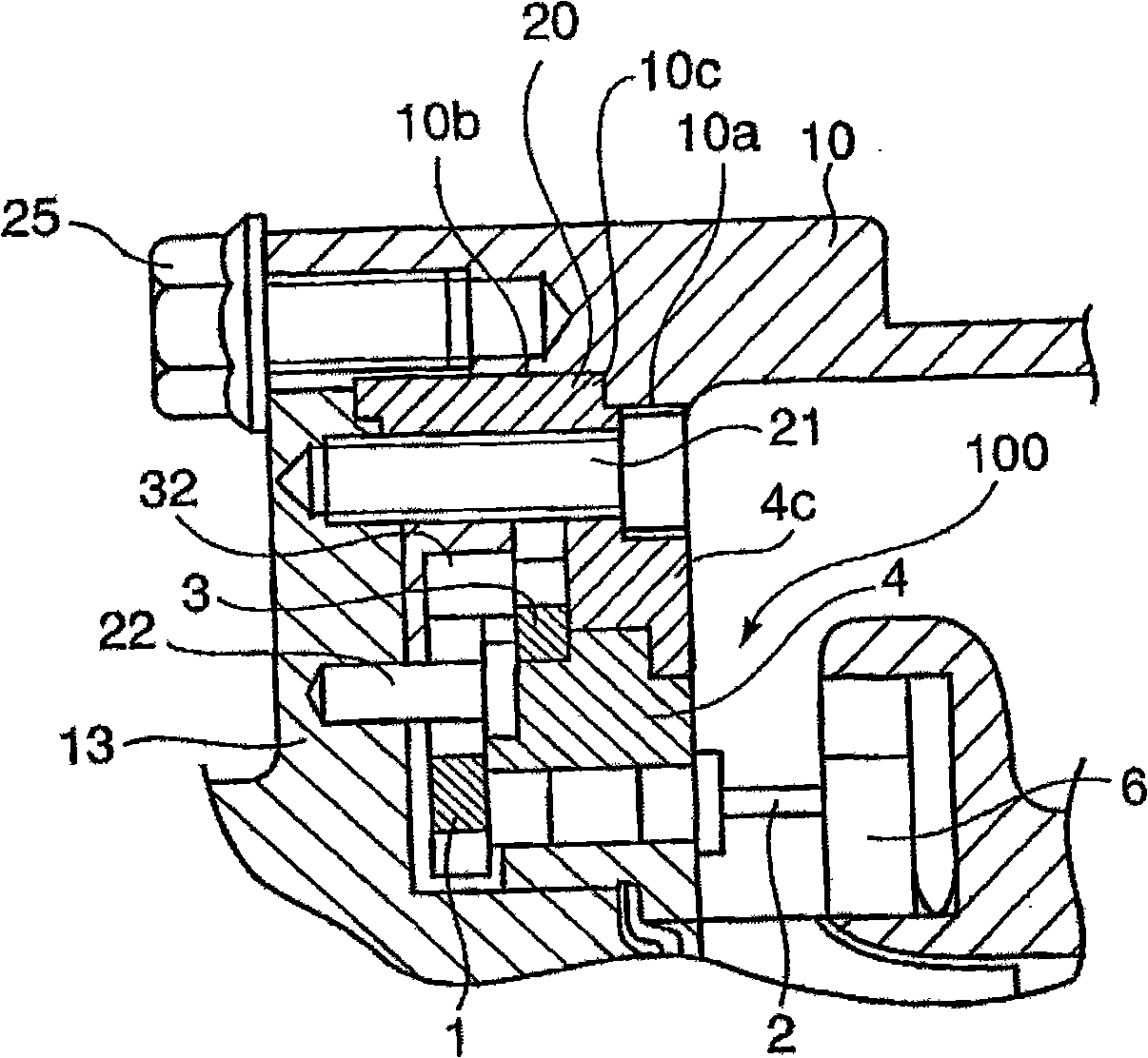
[0070] refer to figure 1 and 2 , an insert 20 forming a ring shape is removably connected to the side surface of the bearing housing 13 at the outer periphery of the spout holder 4 by a plurality of fixing screws (nuts) 21 arranged circumferentially. Thus, by fastening said insert 20 to the bearing housing 13 which can be kept at a low temperature, the amount of heat conducted from the high temperature turbine casing 10 can be reduced. In addition, by arranging the fixing screw 21 at a position adjacent to the spout holder 4, the spout assembly can avoid deformation or movement as much as possible.
[0071]The turbine housing 10 is formed therein with a connection hole 10 a having a diameter substantially equal to the outer diameter of the scroll 11 extending from the scroll 11 to the bearing housing 13 . The outer peripheral portion 20 of the insert 20 is fitted in the connection hole 10a at the inner circumference of the connection hole 10a in a spigot configuration. The ...
no. 2 example
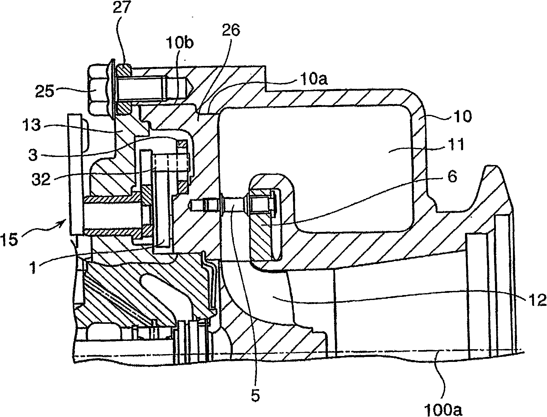
[0080] image 3 is a longitudinal sectional view of the essential part of the upper half on the turbine side of the second embodiment of the present invention.
[0081] In this second embodiment, an integrated spout holder type insert 26 is provided, wherein the spout holder 4 and the insert 20 described in the first embodiment are integrally combined with each other. The above-mentioned one-piece spout bracket type insert 26 is fitted at its outer periphery in a connecting hole 10 a formed in the turbine housing 10 and opening from the scroll 11 toward the bearing housing 13 . Furthermore, said integral spout holder type insert 26 is connected to the bearing housing 13 by a plurality of fixing screws (cap screws) 21 as explained in the first embodiment.
[0082] The integral nozzle bracket type insert 26 described above is secured to the turbine casing 10 fastened together with the outer peripheral flange of the bearing housing by bolts 25 through ring locks 27 .
[0083] I...
no. 3 example
[0087] Figure 4 is displayed corresponding to figure 2 A view of a third embodiment of the invention.
[0088] In the third embodiment, the insert 20 is formed in its outer peripheral portion with a flange 20s that is clamped between flanges formed at the outer periphery of the turbine casing 10 and the bearing housing 13. Between them, the parts thus clamped are joined together in a fluid-tight manner at their outer peripheries by connecting pieces 28 . Except for this structure, the configuration of the third embodiment is the same as that of the first embodiment, and therefore, the same reference numerals are used to denote the same components explained in the first embodiment.
[0089] In the third embodiment as described above, since the insert 20 can be connected in a fluid-tight manner by only a single connection piece 28, the number of constituent parts can be reduced. In addition, in the third embodiment, the three members, that is, the insert 20, the turbine hou...
PUM
 Abstract
Description
Claims
Application Information
 - R&D
- Intellectual Property
- Life Sciences
- Materials
- Tech Scout
- Unparalleled Data Quality
- Higher Quality Content
- 60% Fewer Hallucinations
Browse by: Latest US Patents, China's latest patents, Technical Efficacy Thesaurus, Application Domain, Technology Topic, Popular Technical Reports.
© 2025 PatSnap. All rights reserved.Legal|Privacy policy|Modern Slavery Act Transparency Statement|Sitemap|About US| Contact US: help@patsnap.com


