Temporary micro building structure capable of extending and retracting vertically

A kind of building structure and temporary technology, applied in the direction of building components, sustainable buildings, residential buildings, etc., can solve the problems of unfavorable heat preservation, difficult space height, unfavorable ventilation, etc., achieve high market implementation possibility and convenient construction , low-cost effect

Active Publication Date: 2020-08-25
YANGZHOU UNIV
View PDF6 Cites 3 Cited by
  • Summary
  • Abstract
  • Description
  • Claims
  • Application Information

AI Technical Summary

Problems solved by technology

Its disadvantages are: due to the difference in seasonal environmental conditions, the difference in use purposes and the need to save land, it is difficult to temporarily adjust the height of the building space, which is not conducive to keeping warm in winter and not conducive to ventilation in summer

Method used


Image

  • Temporary micro building structure capable of extending and retracting vertically
  • Temporary micro building structure capable of extending and retracting vertically
  • Temporary micro building structure capable of extending and retracting vertically

Examples


Embodiment 1

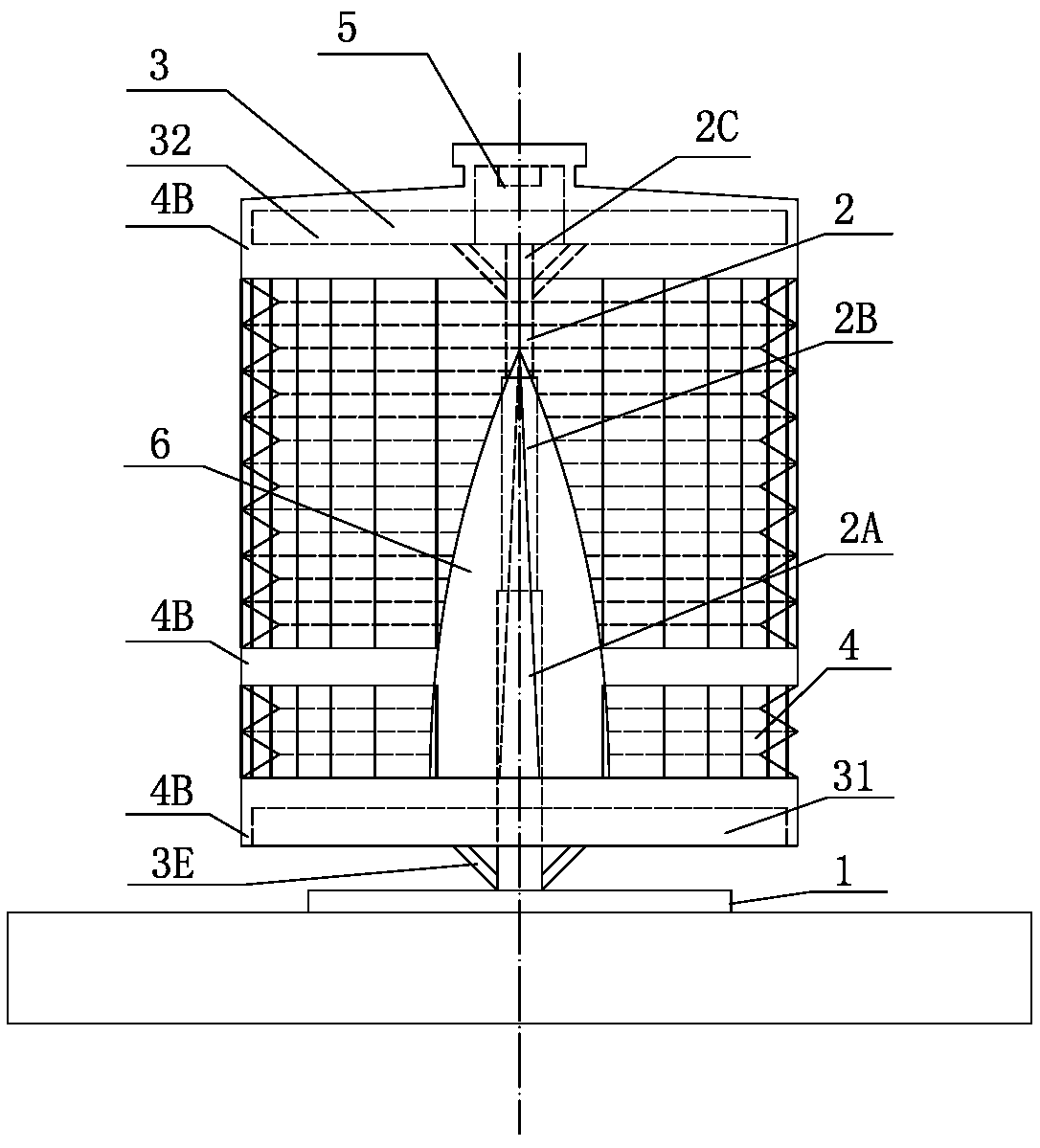
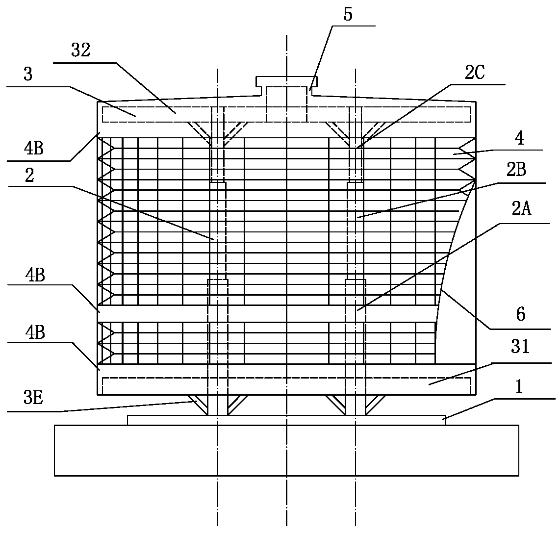
[0052] Such as Figure 10-16 , the building structure can stretch or shrink the flexible wall structure 4 according to the actual needs of users to adjust the height of the building, which can be divided into the following four working states:

[0053] Working state-summer working state: At this time, the building needs a larger height to enhance the natural ventilation caused by heat and pressure, making the interior cooler. Figure 10 It is the cross-sectional view of the building in the summer working condition; Figure 11 It is the longitudinal section of the building in summer working condition; Figure 12 It is the cross-sectional view of the skeleton structure in the summer working condition; Figure 13 It is a longitudinal section view of the skeleton structure in summer working conditions.

[0054] Working status 2 Transition season working condition: At this time, the building needs a moderate height to make the indoor temperature suitable. Figure 14 It is a cro...

Embodiment 2

[0058] Such as Figure 17-20 According to the actual needs of users, this building can add intermediate floor slabs 33 in the building to increase the number of building floors. A telescopic ladder needs to be erected at the opening of the middle floor slab 33. Figure 17 is a cross-sectional view of a two-storey building; Figure 18 is a longitudinal section of a two-storey building; Figure 19 A cross-sectional view of the skeleton structure of a two-storey building; Figure 20 It is a longitudinal section view of the skeleton structure of a two-storey building.


PUM


Abstract

The invention discloses a temporary micro building structure capable of extending and retracting vertically, and belongs to the field of building structures. The temporary micro building structure comprises a base, a telescopic column, a floor structure system, a flexible wall surface structure, a ventilation structure and an elastic door, wherein the telescopic column can extend and retract in the height direction; a plurality of first through holes and second through holes are formed pairwise in the telescopic column; a main straight beam in the floor structure system is inserted into the first through holes; two of auxiliary straight beams are inserted into corresponding second through holes; ring beams, the main straight beam and the auxiliary straight beams are integrally constructedinto a grid structure, and are fixed with one another at intersection points; a panel is paved above the grid structure; the ventilation structure is formed on the top; the flexible wall surface structure is adopted on the outer side; and the elastic door is arranged on the flexible wall surface. According to the temporary micro building structure, the floor height and floor number of a building can be adjusted at any time according to the demands of a user; the living comfort of the user is improved through combination of ventilation, heat insulation and other measures; and the application performance of the building can be improved greatly.

Description

technical field [0001] The invention relates to the field of building structure design, in particular to a vertically expandable temporary miniature building structure. Background technique [0002] Temporary micro-buildings can be used in tourist attractions, post-disaster resettlement, construction sites and other occasions. It can solve the problem of resettlement for people with housing shortages, and can also meet the individual needs of some people for living space. It has small footprint, low cost, and easy installation. Convenience and other advantages. Its disadvantages are: due to the difference in seasonal environmental conditions, the difference in purpose of use and the need to save land, it is difficult to temporarily adjust the height of the building space, which is not conducive to keeping warm in winter and not conducive to ventilation in summer. Contents of the invention [0003] The purpose of the present invention is to provide a vertically expandable ...

Claims


Application Information

Patent Timeline
Patent Type & Authority Applications(China)
IPC IPC(8): E04H1/04E04B1/343E04B5/00E04B2/00E04B1/76E04D13/16E04F15/02E04F15/18E06B3/30E06B3/70F24S70/20F24F7/007
CPCE04B1/34305E04B1/76E04B2/00E04B5/00E04D13/16E04F15/02E04F15/18E04H1/04E06B3/30E06B3/70F24F7/007F24S70/20Y02B10/20Y02E10/40
Inventor 刘义陈星
Owner YANGZHOU UNIV
Why Eureka
Try Eureka