Method for placing inert gas in gas-filling and packaging machine

一种惰性气体、充气包装的技术,应用在通过加压/气化包装、包装、在特殊气体条件下包装物件等方向,能够解决气体置换率差、填充时间增加、喷嘴扎刺等问题,达到气体置换率提高、充气作业顺畅、简单机械结构的效果

Inactive Publication Date: 2008-09-03
GENERAL PACKER
View PDF2 Cites 10 Cited by
  • Summary
  • Abstract
  • Description
  • Claims
  • Application Information

AI Technical Summary

Problems solved by technology

Therefore, when the former nozzle fixing structure is adopted, since the front end of the nozzle is inserted into the corner of the packaging bag, when the packaging bag is a flat bag or a Figure 8 In the square bag e shown, it is easy to make an insertion error in which the tip of the nozzle n deviates from the opening f of the square bag e.
In addition, in Figure 9 In the illustrated chuck bag a with side gussets in the form of tucked-in portions c on both sides except for the bag opening b, occasionally the front end of the nozzle n is stuck to the tucked-in portions. c Defects such as protruding parts on the inside
[0004] In the case of the latter nozzle fixing structure, since the nozzle fixed at the center of the filling funnel becomes an obstacle when the packaged goods pass through, the filling time increases, resulting in the inconvenience that the packaged goods are clogged in the filling funnel happens sometimes
[0005] In addition, in the inert gas filling method described in the publication, since the gas replacement is not performed in the state where the mouth of the bag is forcibly closed, it can also be said that it may be caused by the type or size of the packaging bag and the type of the packaged object. Poor gas exchange rate

Method used


Image

  • Method for placing inert gas in gas-filling and packaging machine
  • Method for placing inert gas in gas-filling and packaging machine
  • Method for placing inert gas in gas-filling and packaging machine

Examples


Embodiment Construction

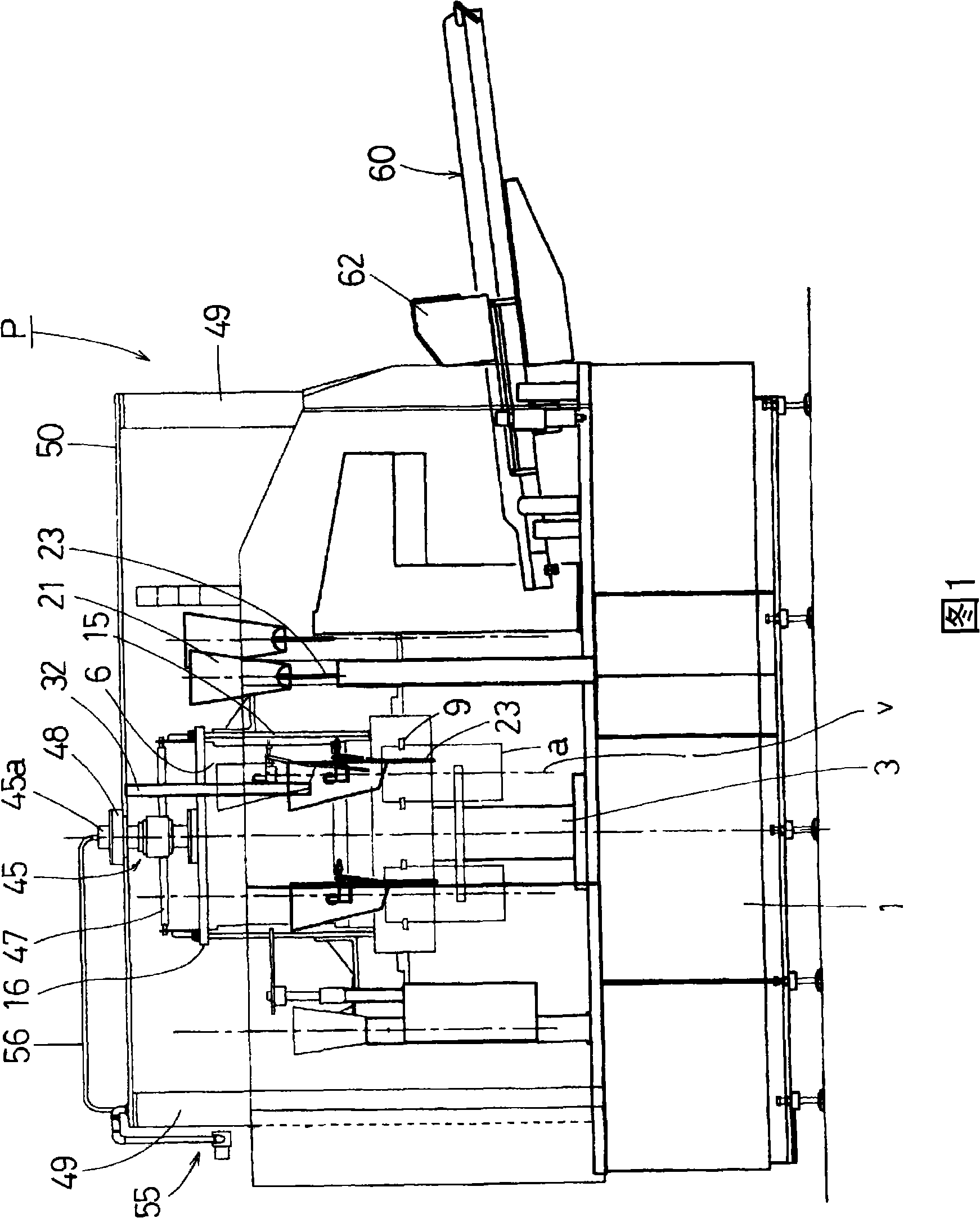
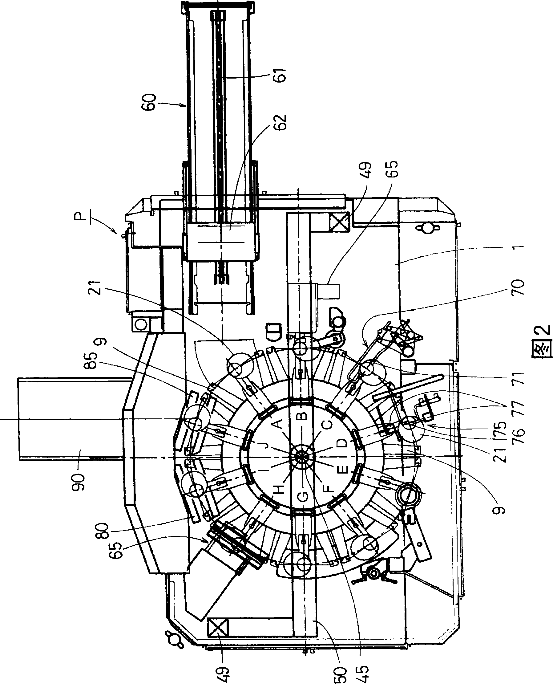
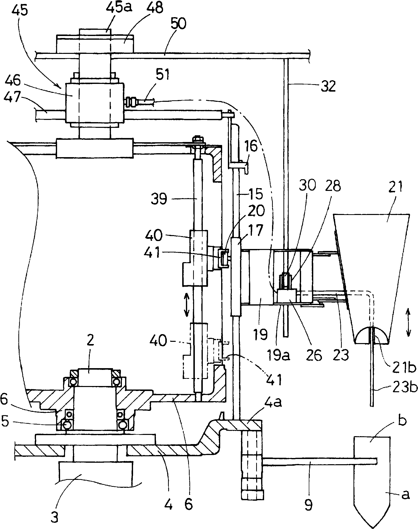
[0015] The preferred embodiment of the present invention will be described below with reference to the accompanying drawings. Fig. 1 is a side view of an air packaging machine employing the inert gas filling method of the air packaging machine of the present invention. Fig. 2 is a plan view of an air packaging machine using the inert gas filling method of the air packaging machine of the present invention. image 3 It is a side view showing the configuration of the rotating body, the filling funnel and its surroundings. Figure 4 It is an explanatory diagram of the nozzle attitude control device. Fig. 5 is a filling hopper and an inflation nozzle, the relative position relationship with the packaging bag, and the expanded view of the cam guide shown in the whole process. Figure 6 It is a partial side view of the shutter device showing a state in which the bag mouth is closed and the gas is replaced. Figure 7 yes Figure 6 A top view of the gate device in .

[0016] An a...


PUM


Abstract

The present invention provides an inert gas placing method for a gas- filling and packaging machine, in which troubles occurring when a gas-filling nozzle is inserted into a packaging bag are eliminated and in which a gas replacement rate is increased. A gas-filling nozzle (23) is provided at a filling funnel (21) in correspondence with each grip (9) of a rotating body, and the gas-filling nozzle (23) has a forward end (23b) controlled by a nozzle attitude control means (25) so as to approach or recede from an imaginary normal line v passing through the center of the drop opening of the filling funnel. In the process preceding a filling process, the drop opening of the filling funnel and the forward end of the gas-filling nozzle brought close to the normal line v are inserted from the opened bag opening b into a package bag a, and at the same time, the forward end is separated from the normal line v and moved toward a corner of the package bag. In the process following the filling process, inert gas jetted from the gas filling nozzle and air in the package bag are replaced with each other, and in a postprocess on the downstream side, the replacement action between the inert gas and the air is promoted with the bag opening b substantially closed by a shutter means (65).

Description

technical field [0001] The present invention relates to an inert gas inert gas packaging machine for sealing the mouth of a packaging bag filled with an object to be packaged by spraying an inert gas from a nozzle to expel the air in the bag to the outside. filling method. Background technique [0002] The invention related to the present applicant is disclosed in JP-A-2004-67224 as an inert gas filling method of a conventional air packaging machine. This inflatable packaging machine uses an intermittent rotary table to perform the filling operation of filling the packaged objects into the packaging bag, the filling operation of filling inert gas such as nitrogen, and the heat sealing operation of heat sealing the mouth of the bag after filling them. Moreover, the nozzle for filling inert gas is fixed on the outer surface of the filling funnel provided on the packaging bag with the opening of the bag in an open state in such a manner that the discharge port can be freely en...

Claims


Application Information

Patent Timeline
Patent Type & Authority Applications(China)
IPC IPC(8): B65B31/04B65B39/12B65B39/14
CPCB65B31/042
Inventor 平野佳史
Owner GENERAL PACKER
Why Eureka
Try Eureka