
Replaceable micro-surgical instrument

a micro-surgical and replacement technology, applied in the field of replacement micro-surgical instruments, can solve the problems of low replacement rate, difficult postoperative healing, and high depletion, and achieve the effect of reducing instrument cost and easy assembly or disassembly

Inactive Publication Date: 2013-12-05
NAT CENT UNIV
View PDF8 Cites 7 Cited by
  • Summary
  • Abstract
  • Description
  • Claims
  • Application Information

AI Technical Summary

Benefits of technology

The present invention provides a micro-surgical instrument with a replaceable micro-surgical element and an elastic element. The elastic element can be easily replaced without replacing the whole instrument, reducing costs and increasing replacement rate. The micro-surgical element can be made of a metallic glass or coated with a metallic glass thin film, resulting in improved sharpness and reduced friction force. The invention also has technical advantages such as high thermo-stability, high tensile strength, high elasticity, and high impact toughness.

Problems solved by technology

Existing micro surgical instruments are usually a single instrument for a single purpose and therefore cause high depletions.
But high price of micro surgical instruments causes low replacement rate and results in unsuccessfully excision of disease tissues or pulling and dragging of healthy organizations, the postoperative healing becomes more difficult.
On the other hand, the surgical instruments used in the surgery are generally made of martensitic stainless steel, a crystalline structure, and its elastic limit is less than 0.5%, and thereby the shift of the normal vector of force away from the center axis often causes the breaking of surgical instruments, resulting in surgical inconvenience.
Because the minimally invasive surgery usually needs to clip or twist the surgical instruments, the shift of force away from the center axis would cause the breaking of the surgical instruments, resulting in failure of the surgery and even medical disputes.

Method used


Image

  • Replaceable micro-surgical instrument
  • Replaceable micro-surgical instrument
  • Replaceable micro-surgical instrument

Examples


Embodiment Construction

[0022]Hereinafter, the present invention will be described in further detail with reference to examples and comparative examples. It is to be understood, however, that these examples are illustrative only and the scope of the present invention is not limited thereto. Those skilled in the art will appreciate that various modifications, additions and substitutions are possible, without departing from the scope and spirit of the invention as disclosed in the accompanying claims.

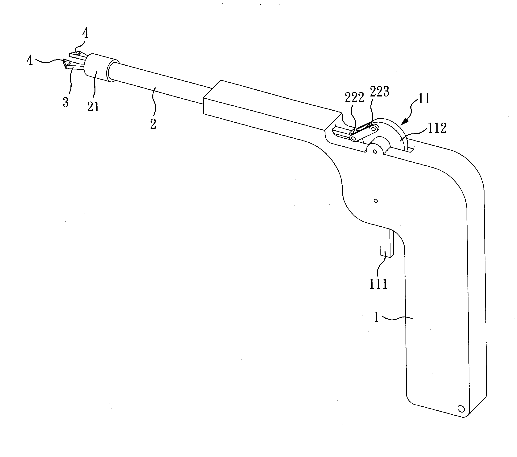
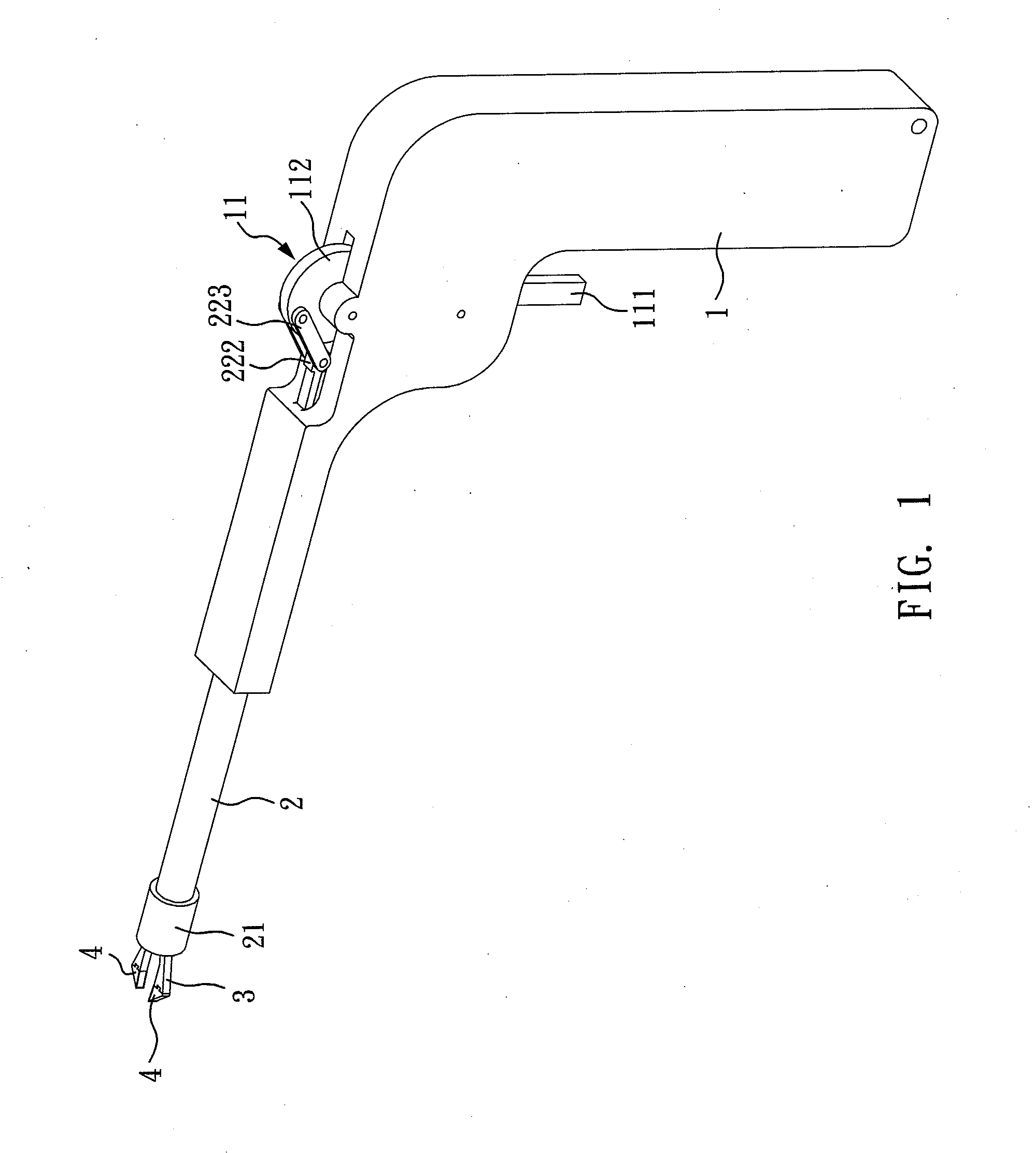
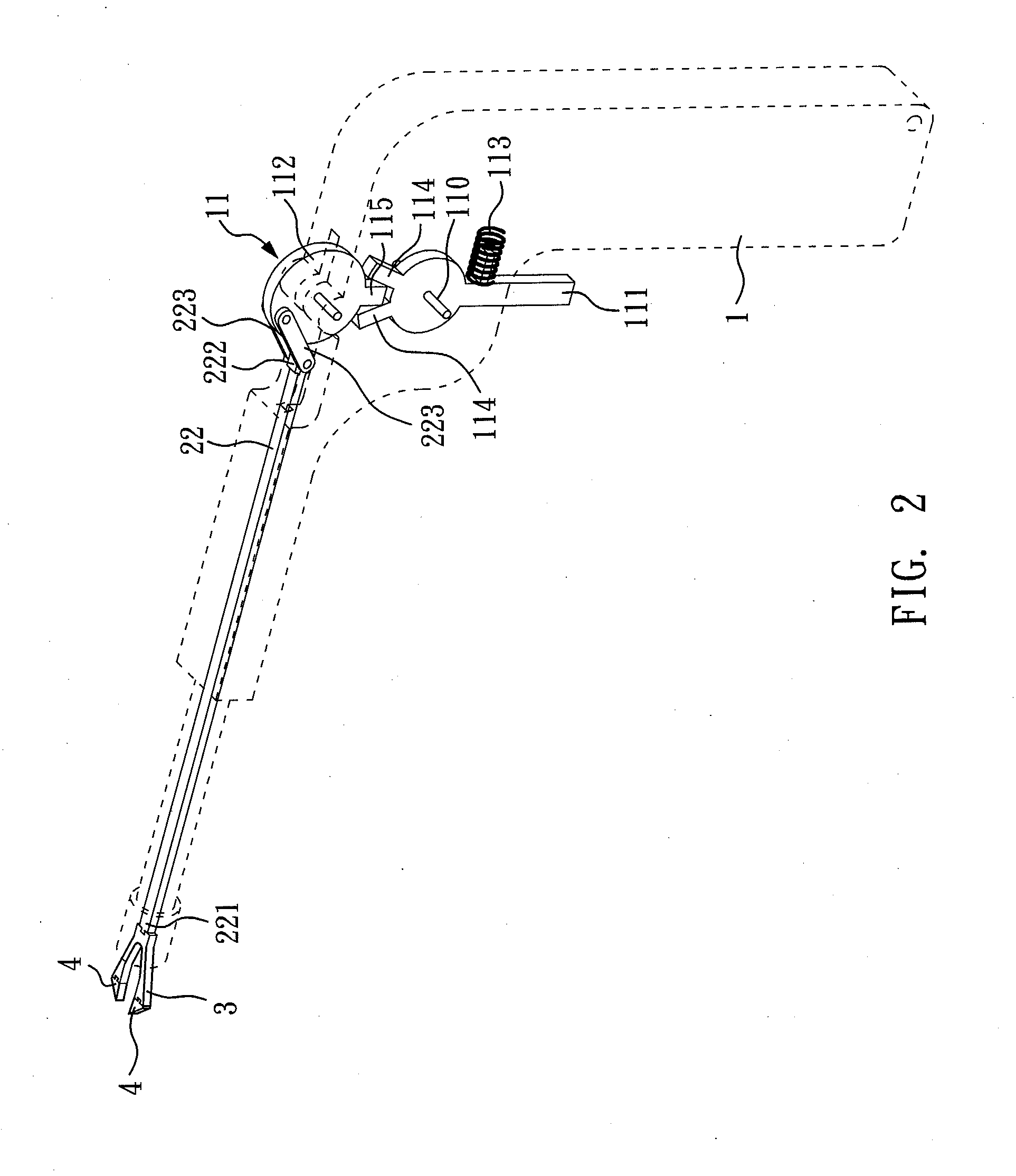
[0023]Please referring to FIG. 1 and FIG. 2, FIG. 1 and FIG. 2 both are a perspective view of a replaceable micro-surgical instrument according to a first preferred embodiment of the present invention. The replaceable micro-surgical instrument of the first embodiment of the present invention comprises a grip 1, a pull structure 11, and a hollow tube 2. The hollow tube 2 has a sleeve 21 at one end with a U-type elastic element 3 sliding set in the sleeve 21 and another end of the hollow tube 2 attached to the gri...


PUM


Abstract

The present invention provides a replaceable micro-surgical instrument which comprises a pull structure and a hollow tube attached to a grip. The hollow tube has a sleeve at one end with a U-type elastic element sliding in. The U-type elastic element includes a spring tension section and two opposite extending arms and the outer edge of each arm is against the inner wall of the sleeve. Two arms could move according to the pull structure to selectively extend out of the sleeve to be opened or pull back into the sleeve to be clip together. Particularly, there is a replaceable micro-surgical element set in the front-end of each arm, so when the micro-surgical element becomes blunt or broken, the doctor could only replace the micro-surgical element without replace a whole new instrument in order to reduce instrument cost, increase replacement rate, and maintain the quality of medical surgery.

Description

CROSS REFERENCE TO RELATED APPLICATION[0001]This application claims the benefits of the Taiwan Patent Application Serial Number 101119317, filed on May 30, 2012, the subject matter of which is incorporated herein by reference.BACKGROUND OF THE INVENTION[0002]1. Field of the Invention[0003]The present invention relates to a replaceable micro-surgical instrument, more particularly, to a surgical instrument having replaceable micro-surgical elements.[0004]2. Description of Related Art[0005]In present medical surgery, micro surgical instruments are often used in the surgery related to chest or abdomen treatment, such as cutting disease tissues using a micro cutting tool. Existing micro surgical instruments are usually a single instrument for a single purpose and therefore cause high depletions. But high price of micro surgical instruments causes low replacement rate and results in unsuccessfully excision of disease tissues or pulling and dragging of healthy organizations, the postoperat...

Claims


Application Information

Patent Timeline
IPC IPC(8): A61B17/00A61B17/32A61B17/29
CPCA61B17/00234A61B17/2909A61B17/320016A61B17/29A61B2017/00473A61B2017/00845A61B2017/00964A61B2017/2919A61B2017/292A61B2017/305
Inventor JANG, JASON SHIANG CHINGTSAI, PEI-HUALI, JIA-BINWONG, PEI-CHUNHUANG, CHIH-CHING
Owner NAT CENT UNIV
Learn More